19
Introduction
The Giant Magnetoresistance (GMR) refers to the phenomenon in which the electrical resistivity of a magnetic material changes greatly when it has an external magnetic field as compared with the absence of an external magnetic field.
It is a quantum mechanical effect that results from a layered magnetic thin film structure. This structure is formed by alternately laminating thin layers of ferromagnetic material and non-ferromagnetic material. When the magnetic moments of the ferromagnetic layers are parallel to each other, the carrier-dependent scattering is minimal and the material has the smallest resistance. When the magnetic moment of the ferromagnetic layer is anti-parallel, the spin-related scattering is the strongest and the resistance value of the material is the largest. There are many kinds of giant magnetoresistance materials at room temperature, such as multilayer giant magnetoresistance materials, granular giant magnetoresistance materials, oxide giant magnetoresistance materials, tunnel junction magnetoresistance materials and so on.
Catalog
Introduction | |
I Definition of the Giant Magnetoresistance (GMR) | |
II The Discovery of the Giant Magnetoresistance (GMR) | |
III The Phenomenon of the Giant Magnetoresistance (GMR) | |
IV The Features of the Giant Magnetoresistance (GMR) | |
Ⅴ The Principle of the Giant Magnetoresistance (GMR) | 5.1 Scattering on the Surface |
5.2 Scattering in a Ferromagnetic Film | |
Ⅵ Giant Magnetoresistance (GMR) and Layer Structure Analysis | |
Ⅶ The Measurement of the Giant Magnetoresistance (GMR) | |
Ⅷ The Application of the Giant Magnetoresistance (GMR) | 8.1 GMR Sensor |
8.2 High Density and Ultra High Density Magnetic Recording Read Head | |
8.3 MRAM |
ⅠThe Definition of the Giant Magnetoresistance (GMR)
Giant Magnetoresistance (GMR) is a phenomenon of quantum mechanics and condensed matter physics. It is a kind of magnetoresistance effect that can be observed in thin film layers (several nanometers thick) between magnetic and non-magnetic materials. In October 2007, the French scientist Albert Fert and the German scientist Peter Andreas Grunberg jointly won the 2007 Nobel Prize in Physics for their independent discovery of the Giant Magnetoresistance.
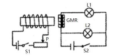
The resistance value of the structure material is related to the magnetization direction of the ferromagnetic thin film. The resistance value of the two layers of magnetic material in opposite magnetization direction is obviously larger than that of the same magnetization direction. The resistance varies greatly under very weak external magnetic field. Giant Magnetoresistance materials have broad application prospects in data read heads, magnetic random access memories and sensors.
II The Discovery of the Giant Magnetoresistance (GMR)
The Giant Magnetoresistance was independently discovered in 1988 by Peter Andreas Grunberg of the Yulich Research Center in Germany and by Albert Fert of the Eleventh University in Paris. They jointly won the 2007 Nobel Prize in Physics.
In the initial work, Peter Andreas Grunberg's research team only studied structural materials composed of three layers of iron, chromium and iron. Their experimental results showed that the electrical resistance value was decreased by 1.5%. While Albert Fert 's team studied multilayer materials made of iron and chromium, which reduced the resistance value by 50%.
Andreas Grunberg and the Yullich Research Center had a patent for giant magnetoresistance technology, and his original paper was submitted a little earlier than Fert's (Andreas Grunberg’s on 31 May 1988, Fert's on 24 August 1988). But Fert's article was published earlier (Andreas Grunberg’s in March 1989, Fert's in November 1988). Fert accurately described the physical principles behind the giant magnetoresistance phenomenon, while Andreas Grunberg quickly found the importance of the giant magnetoresistance in technical applications.
III The Phenomenon of the Giant Magnetoresistance (GMR)
The phenomenon that the resistance value of a substance changes under a certain magnetic field, known as the“magnetoresistive effect”. Magnetic metals and alloy materials generally have such a magnetoresistance phenomenon. Generally, the resistivity of a substance only slightly decreases in the magnetic field.
Under certain conditions, the resistivity decreases by a considerable extent, more than 10 times higher than the magnetoresistance value of magnetic metal and alloy materials, called "Giant Magneto Resistance" (GMR); and in a strong magnetic field, some of the insulators suddenly become conductors, called "Colossal magnetoresistance".
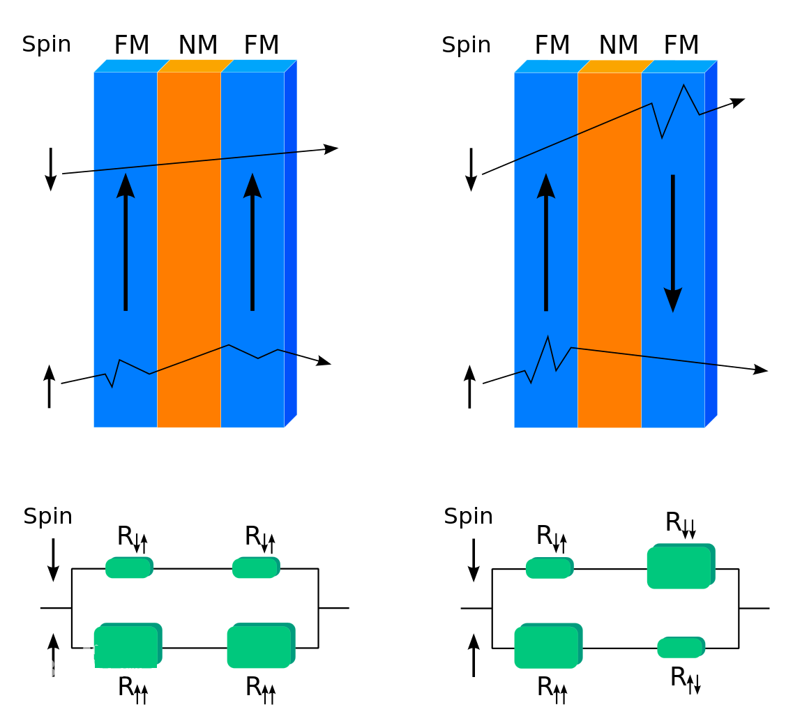
Diagram of the GMR
As shown in the figure above, the materials on the left and right sides have the same structure, with a thin film of magnetic material (blue) on both sides and a thin film layer of non-magnetic material (orange) in the middle.
In the left side of the structure, the magnetization directions of the two layers of magnetic material are the same.
(1)When a beam of electrons with the same direction of spin and magnetic direction of the magnetic material passes, it is easier for the electrons to pass through the two layers of magnetic material, presenting the small resistance value.
(2)When a beam of electrons whose spin direction is opposite to the magnetization direction of the magnetic material passes, it is difficult for electrons to pass through the two layers of magnetic material, presenting the large resistance value. This is because the spin direction of the electron is opposite to the magnetization direction of the material, resulting in scattering and decreasing the number of electrons passing through, thus reducing the current.
In the right side of the structure, the magnetization directions of the two layers of magnetic material are opposite.
(3) When a beam of electrons with the same spin direction as that of the first layer of magnetic material passes through, it is easier for the electrons to pass through and present the small resistance value; but it is difficult to pass through the magnetic material of the second layer whose magnetization direction is opposite to the direction of the electron spin, presenting the large resistance value.
(4)When a beam of electrons whose spin direction is opposite to the direction of magnetization of the first layer of magnetic material passes, it is difficult for the electron to pass through, presenting the large resistance value; but it is easier to pass through the magnetic material of the second layer whose magnetization direction is same as the direction of the electron spin, presenting the small resistance value.
IV The Features of the Giant Magnetoresistance (GMR)
The giant magnetoresistance is a quantum mechanical and condensed matter physics phenomenon, a kind of magnetoresistance effect, which can be observed in the thin film layer (several nanometer thick) structure between the magnetic material and the nonmagnetic material.
![]()
Magnetoresistance Effect
The resistance value of the structure material is related to the magnetization direction of the ferromagnetic thin film. The resistance value of the two layers of magnetic material in opposite magnetization direction is obviously larger than that of the same magnetization direction. The resistance varies greatly under very weak external magnetic field.
Ⅴ The Principle of the Giant Magnetoresistance (GMR)
According to the microscopic mechanism of conduction, the electrons in the metals do not travel straight along the electric field when conducting electricity, but continuously collide with the atoms in the lattice position (also called scattering), and the electrons change the direction of motion after each scattering. The motion is the superposition of the directional acceleration of the electric field on the electrons. After each scattering, electrons will change their direction of motion. The average distance of the electrons moving between the two scatterings is called the mean free path. The smaller the probability of electron scattering is, the longer the mean free path is and the lower the resistivity is.
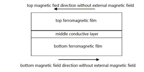
Figure 4. Structural Charts of Multilayer GMR
As shown in Figure 4, in the multi-layer GMR structure, when there is no external magnetic field, the magnetic moments of the upper and lower ferromagnetic films are anti-parallel (antiferromagnetic) coupled because the energy is minimal. Under the action of a sufficiently strong external magnetic field, the direction of the magnetic moment of the ferromagnetic film is consistent with the direction of the external magnetic field, and the external magnetic field changes the two layers of ferromagnetic film from anti-parallel coupling to parallel coupling.
There are two types of spin-dependent scattering that contribute to the giant magnetoresistance effect.
5.1 Scattering on the Surface
When there is no external magnetic field, the magnetic fields of the upper and lower ferromagnetic films are opposite in direction. Regardless of the initial spin state of the electrons, the state changes from a ferromagnetic film to another ferromagnetic film(parallel → anti-parallel or anti-parallel → parallel). The scattering probability of the electrons on the surface is very large, which corresponds to the high resistance state. When there is an external magnetic field, the magnetic fields of the upper and lower ferromagnetic films are in the same direction, and the scattering probability of electrons on the interface is very small, which corresponds to the low resistance state.
5.2 Scattering in a Ferromagnetic Film
Because of random scattering, electrons also have a certain probability to travel between the upper and lower layers of ferromagnetic films. When there is no external magnetic field, the magnetic fields of the upper and lower ferromagnetic films are opposite in direction. Regardless of the initial spin state of the electrons, there are two processes of small scattering probability (parallel) and large scattering probability (anti-parallel) during the traveling process. The parallel resistance of a spin-like electron current is similar to the parallel connection of two medium-resistance resistors, corresponding to a high resistance state. When there is an external magnetic field, the magnetic fields of the upper and lower ferromagnetic films are in the same direction, the scattering probability of spin parallel electrons is small, and the scattering probability of spin anti parallel electrons is large. The parallel resistance of the two kinds of spin electrons is similar to that of a small resistance and a large resistance, which corresponds to the low resistance state.
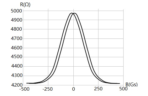
Figure 5. characteristic curve of GMR
Figure 5. shows the magnetoresistance of a GMR material of the structure of Figure 4.
As seen from the direction of the forward magnetic field in the figure, as the external magnetic field increases, the resistance gradually decreases (solid line in the figure), and there is a linear region. When the external magnetic field has made the magnetic field directions of the two ferromagnetic films completely parallel coupling, the magnetic field continues to increase and the resistance no longer decreases, reaching the state of magnetic saturation. Decreasing the magnetic field from the magnetic saturation state, the resistance will gradually increase (dotted line in the figure). The two curves do not coincide because of the hysteresis characteristics of ferromagnetic materials. The magnetoresistance characteristics are symmetrical when the reverse magnetic field and the forward magnetic field are added. As shown in FIG. 5, the two curves correspond to the magnetoresistance characteristics of increasing the magnetic field and reducing the magnetic field.
The giant magnetoresistance (GMR) is realized by changing the relative orientation of the magnetic field of the two ferromagnetic layers in the GMR of all multilayer structures, but the coupling state of the structure and the absence of the external magnetic field is different, as shown in FIG. 4.
For example, the GMR of the spin valve structure is composed of a pinning layer, a pinned layer, an intermediate conductive layer and a free layer. Among them, the pinning layer uses an antiferromagnetic material, the pinned layer uses a hard ferromagnetic material, ferromagnetic and the antiferromagnetic material forms a deflection field under exchange coupling. The deflection field will be fixed by the magnetization direction of the pinned layer and will not change with the external magnetic field. The free layer uses a soft ferromagnetic material, and its magnetization direction is easy to rotate with the external magnetic field. Therefore, a weak external magnetic field changes the relative orientation of the free layer and the magnetic field of the pinned layer, which corresponds to a high sensitivity, and this structure is adopted for the GMR head used for the hard disk.
Ⅵ The Layer Structure Analysis of the Giant Magnetoresistance (GMR)
The magnetoresistance is a phenomenon in which the resistance value of a body or a semiconductor changes under the action of a magnetic field. It has been found that in magnetic multilayer films such as Fe/Cr and Co/Cu, the ferromagnetic layer is separated by non-magnetic materials with thickness of nanometers. Under certain conditions, the magnitude of the decrease in resistivity is quite large, which is about 10 times higher than the magnetoresistance of magnetic materials and alloy materials. This phenomenon is called "giant magnetoresistance".
The giant magnetoresistance can be explained by quantum mechanics. Each electron can spin, and the scattering rate of electrons depends on the direction of the spin and the direction of magnetization of the magnetic material. When the spin direction is the same as the magnetization direction of the magnetic material, the electron scattering rate is low, and there are more electrons passing through the magnetic layer, resulting in a low impedance. On the contrary, when the spin direction is opposite to the magnetization direction of the magnetic material, the electron scattering rate is high, and there are fewer electrons passing through the magnetic layer, resulting in a high impedance.
The sensor based on the giant magnetoresistance effect has three layers of inductive materials: Reference Layer or Pinned Layer, Normal Layer and Free Layer. As shown in Figure 6., the reference layer has a fixed magnetization direction, and its magnetization direction is not affected by the direction of the external magnetic field. The normal layer is the non-magnetic material film, which separates two layers of magnetic material film. The direction of the free layer magnetic field changes as the direction of the parallel magnetic field changes.
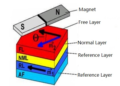
Figure 6. The Layer Structure of the GMR
As shown in Figure 7., the blue layer on both sides represents a thin film layer of magnetic material, and the orange layer in the middle represents a film layer of non-magnetic material. The green arrow represents the magnetization direction of the magnetic material, the gray arrow represents the spin direction of the electron, and the black arrow represents the electron scattering. The left diagram shows that the magnetization directions of the two layers of magnetic materials are the same. When a beam of electrons with the same spin direction and the magnetization direction of the magnetic material passes through, the electrons easily pass through the two layers of magnetic material, thus presenting a low impedance. While the right diagram figure shows that the magnetization directions of the two layers of magnetic materials are opposite. When a beam of electrons whose spin direction is the same as the magnetization direction of the first layer of magnetic material passes through, the electrons are easier to pass through. However, it is difficult to pass through the second layer of magnetic material which has opposite direction of magnetization and electron spin, thus presenting a high impedance.
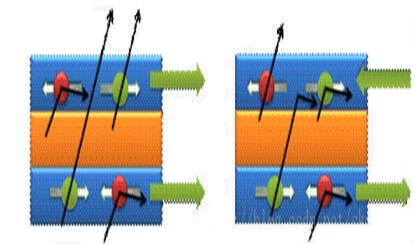
Figure 7. Schematic Diagram of Electron Spin and Magnetization Direction
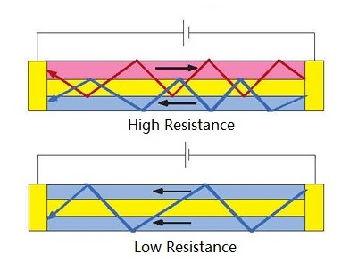
As shown in Figure 8, A is a conductive non-magnetic thin film. In the state where no external magnetic field is applied,the antiferromagnetic coupling makes the direction of the magnetic moment in the B layer on both sides in the opposite state. At this time, the current flowing through the element presents a high resistance state.
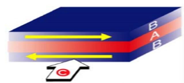
Figure 8. High Resistance Form
As shown in Figure 9, when a magnetic field larger than the antiferromagnetic coupling acts on the giant magnetoresistive element, the direction of magnetization of the free layer is aligned with the direction of the external magnetic field. At this time, the resistance drops sharply and presents a low resistance state to the outside.
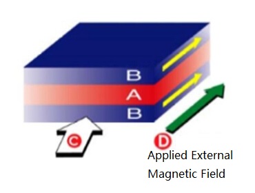
Figure 9. Low Resistance Form
Ⅶ The Measurement of the Giant Magnetoresistance (GMR)
Place the GMR in the solenoid magnetic field. The direction of the magnetic field is parallel to the plane of the film, and a constant voltage is applied across the reluctance. The initial magnetization direction of the GMR ferromagnetic film is perpendicular to the direction of the magnetic field, adjust the coil current, gradually reduce the magnetic induction from positive to negative, record the reluctance current and calculate the reluctance. Then gradually increase the magnetic induction and record the corresponding value.
The change of resistance in different external magnetic field reflects the magnetoresistance characteristics of GMR. The difference of magnetoresistance under the same external magnetic field reflects the hysteresis characteristics of the material.
Ⅷ The Application of the Giant Magnetoresistance (GMR)
The giant magnetoresistance has been used since its discovery to develop and research small and sensitive data read head for hard disks.
The following will briefly introduce the application of GMR effect in three aspects.
8.1 GMR Sensor
There are two kinds of traditional magnetoresistance sensors: semiconductor (InSb) and soft magnetic alloy. The semiconductor magnetoresistive element has the advantages of large MR and good linearity, but the required magnetic field is high and the temperature stability is poor; The soft magnetic alloy thin film element is high because of its low saturation, but its MR value is not high.
GMR element has the characteristics of huge GMR value and high magnetic field sensitivity. They are used to replace traditional magnetoresistive sensors, which can greatly improve the resolution, sensitivity and accuracy of the sensor. Especially in the sensing of weak magnetic fields, it shows greater superiority. The magnetic rotary encoder made of GMR material not only has the characteristics of high sensitivity and good accuracy, but also has the ability of resisting high temperature, corrosion and other harsh environments. It can replace the photoelectric encoder with poor resistance to harsh environments. Therefore, it is widely used in displacement, speed, acceleration, angle and speed sensors in the fields of automotive electronics technology and mechatronics control.
Two Different Ferromagnetic Materials Sandwiched by a Thin Conduction Layer
8.2 High Density and Ultra High Density Magnetic Recording Read Head
Conventional electromagnetic induction heads, when reading high-density magnetic recording information, the signal-to-noise ratio is no longer satisfactory, because the magnetic flux corresponding to each recording bit is weak at this time. If a thin-film magnetoresistive head is used to read information, the weak change of the magnetic field corresponds to a significant change in the magnetoresistance, which is a relative ideal means for reading high-density magnetic recording information. However, the anisotropic magnetoresistance (AMR) of a conventional thin film magnetoresistive head does not exceed 6% at the maximum, the magnetic field sensitivity of the magnetoresistance change is at most about 0.4%/Oe, and the required external field is about 400 A/m.
These characteristics make the density of magnetic recording information that can be realized by a conventional thin film magnetoresistive magnetic head such as a NiFe alloy film to be limited, and the highest level obtained so far is 3 Gb/in2. The GMR of the giant magnetoresistance film can reach 10% to 30% at room temperature, and the sensitivity of the magnetic field can reach 1 to 8%/Oe. Therefore, it is very competitive on ultra-high density magnetic recording read head.
8.3 MRAM
At present, computer RAM mostly uses dynamic and static random memory (DRAM and SRAM) composed of si integrated circuits. The DRAM has large storage capacity and low price, but the speed is slow (about 10 ms). SRAM can achieve nanosecond speed, but the storage density is slightly lower and the price is more expensive. In the past few years, the MRAM, which is developed with anisotropic magnetoresistance and is not easily lost, has non-destructive readout information and radiation resistance. However, it can not compare with DRAM in terms of storage capacity and storage speed. The discovery of GMR brings new dawn to this kind of magnetoelectronic devices and makes them develop rapidly.
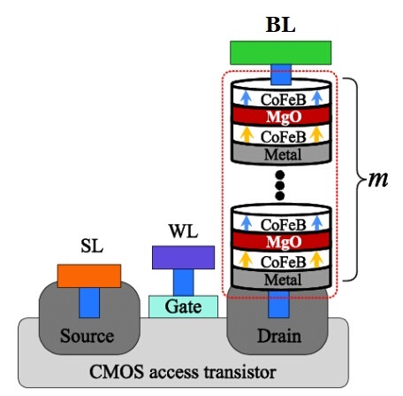
Schematic of the Proposed DFSTT-MRAM Cell Structure
The discovery of the GMR effect has only been more than a decade, but it has made great progress both in basic research and in application development, fully demonstrating the vitality and broad application background of this new functional material. In addition, most of the GMR film materials are prepared by magnetron sputtering technology, which makes the manufacturing of GMR components compatible with the manufacturing process of semiconductor integrated circuits and convenient for industrial mass production.
You May Also Like:
How to Test Different Kinds of Resistors with a Pointer Multimeter
What Are the Functions and Applications of the Varistor?
How to Test Ground Resistance?
The Pull-up Resistor and Pull-down Resistor
Ordering & Quality
| Photo | Mfr. Part # | Company | Description | Package | Qty |
|
DSPB56374AE | Company:NXP / Freescale | Remark:IC DSP 24BIT 150MHZ 52-LQFP | Package:52-LQFP |
DSPB56374AE Datasheet |
In Stock:10211 Inquiry |
Inquiry |
|
SLB 9635 TT1.2 FW3.17 | Company:Infineon Technologies | Remark:IC SPECIALIZED | Package: |
SLB 9635 TT1.2 FW3.17 Datasheet |
In Stock:10854 Inquiry |
Inquiry |
|
K9F4G08UOA-P1BO | Company:SAMSUNG | Remark:4G-bit NAND Flash Memory with spare 128M-bit | Package: |
K9F4G08UOA-P1BO Datasheet |
In Stock:5960 Inquiry |
Inquiry |
|
MC9S08SH8CSC | Company:Freescale Semiconductor - NXP | Remark:IC MCU 8BIT 8KB FLASH 8SOIC | Package:8-SOIC (0.154", 3.90mm Width) |
MC9S08SH8CSC Datasheet |
In Stock:11009 Inquiry |
Inquiry |
|
Z8F042ASB020EG | Company:ZiLOG | Remark:IC MCU 8BIT 4KB FLASH 8SOIC | Package:8-SOIC (0.154", 3.90mm Width) |
Z8F042ASB020EG Datasheet |
In Stock:802 Inquiry |
Inquiry |
|
RL7520WS-R10-F | Company:Susumu | Remark:RES SMD 0.1 OHM 2W 3008 WIDE | Package:Wide 3008 (2075 Metric), 0830 |
RL7520WS-R10-F Datasheet |
In Stock:19360 Inquiry |
Inquiry |
|
S912XEQ512J3MAA | Company:NXP / Freescale | Remark:IC MCU 16BIT 512KB FLASH 80QFP | Package:80-QFP |
S912XEQ512J3MAA Datasheet |
In Stock:98 Inquiry |
Inquiry |
|
TMMBAT46FILM | Company:STMicroelectronics | Remark:DIODE SCHOTTKY 100V 150MA MINMLF | Package:DO-213AA (Glass) |
TMMBAT46FILM Datasheet |
In Stock:48488 Inquiry |
Inquiry |
|
MCF51JE256CLK | Company:NXP | Remark:IC MCU 32BIT 256KB FLASH 80LQFP | Package:80-LQFP |
MCF51JE256CLK Datasheet |
In Stock:2091 Inquiry |
Inquiry |
|
MCIMX353DJQ5C | Company:NXP / Freescale | Remark:IC MPU I.MX35 532MHZ 400MAPBGA | Package:400-LFBGA |
MCIMX353DJQ5C Datasheet |
In Stock:24833 Inquiry |
Inquiry |