23
Resistors are one of the most basic components in electronic circuits. Testing resistors is the basic skill for mastering and learning electronic technology. The testing methods and experience of common resistors are introduced in the following.

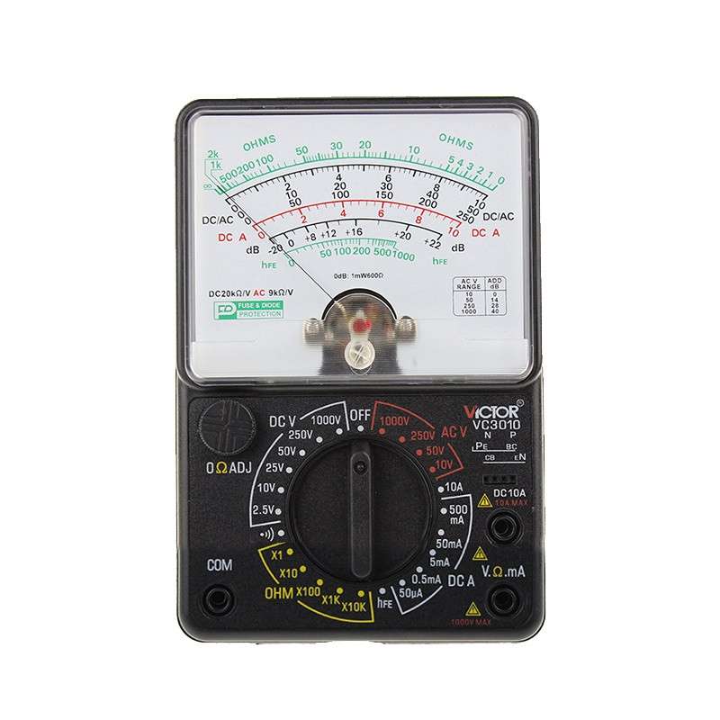
A Pointer Multimeter
Catalog
I Fixed resistors |
II Fuse resistors |
III Potentiometers |
IV Positive Temperature Coefficient (PTC) Thermistors |
V Negative Temperature Coefficient (NTC) Thermistors |
VI Varistors |
VII Photoresistors |
I Fixed resistors
1.1 Testing Method
The actual resistance value can be measured by connecting the two test leads (without distinction between positive and negative terminals) to the two leads of the resistor. In order to improve the measurement accuracy; the range should be selected according to the nominal value of the resistance.
1.2 Testing Experience
(1) Due to the nonlinear relationship of the scale of resistance gear; its middle section is more subtly distributed, so the indicated value of the pointer should falls asmuch as possible to the middle position of the scale, which is in the range of 20%-80% radians of the full scale, to make the measurement more accurate. Depending on the level of resistance error, an error of 5%, ±10% or ±20% is allowed between the reading and the nominal resistance. If the reading number exceeded the error range, it indicates that the resistance value is changed.
(2) When testing, especially when measuring the resistors of resistance above tens of k ohms, do not touch the conductive part of the test leads and the resistor. And when the resistor is welding from the circuit, at least one end must be welded to avoid the influence from other components of the circuit on the test, resulting in a measurement error. Although the resistance of the color ring resistor can be determined by the color circle mark, it is better to use a multimeter to measure its actual resistance value. And for the detection of cement resistors, since theyr are also kind of fixed resistors, the measuring method is exactly the same as the ordinary fixed resistors.
![]()
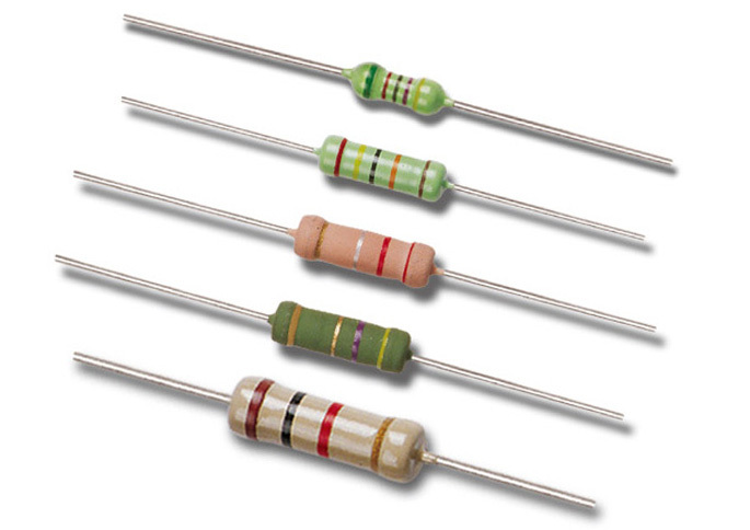
Fixed Resistors
II Fuse resistors
2.1 Testing Method
(1)In the circuit, when the fuse resistor is melted and then disconnect the circuit, the resistance value can be estimate according to personal experience; if the surface of the fuse resistor is found to be black or burnt, it can be concluded that it’s overloaded, which means the current passing through it exceeds the rated value many times. If the surface clean without any trace, it means that the current flowing through it is just equal to or slightly larger than its rated melting value.
(2) The gear of “Rxl” on the multimeter can be used to measure the resistance value of the fuse resistors with no trace on the surface. To ensure the measurement is accurate, one end of the fuse resistor should be soldered from the circuit. If the measured resistance is an infinite value, it means that the fuse resistor has failed to open circuit. If the measured resistance value is far from the nominal value, it indicates that the resistance value is changed and the resistor is not suitable for reuse.
2.2 Testing Experience
In practice, there are also few situations when the fuse resistors are broken down or shorted in the circuit.

Fuse Resistors
III Potentiometers
3.1 Testing Method
(1)When inspecting the potentiometer, first turn the handle and try to see if the rotation of the handle is smooth and the switch is flexible. Besides, try to listen to the sound when the switch is turned on or off to see If the "click" sound is clear. And also listen to the sound of the friction between the internal contact points and the resistor body. A rustling sound usually indicates the poor quality of the resistor.
(2) When testing with a multimeter, first select the appropriate resistance gear according to the resistance of the potentiometer to be tested, and then perform the following detecting steps:
1) Use the gear of the multimeter to measure the resistance value at ends "1" and "3". The reading number should be the nominal resistance of the potentiometer. If the pointer of the multimeter does not move or the two reading values are of huge difference, it indicates that the potentiometer is damaged.
2) Check if the movable arm of the potentiometer is in good contact with the resistor disc.
3) Use the gear of the multimeter to measure the resistance value at ends "1" and "2", and turn the rotor 2 of the potentiometer counterclockwise to a position close to "off". At this time, the smaller the resistance value, the better.
4) Slowly clockwise turn the rotor, and during this time, the resistance value should be gradually increased and the pointer in the meter should move smoothly.
5) When the rotor is turned to the extreme position "3", the resistance value should be close to the nominal value of the potentiometer, which is similar to the result when we measure the resistance value at ends "2"and "3".
3.2 Testing Experience
If the pointer of the multimeter has a jumping phenomenon during the rotation of the shaft handle, it indicates that the movable contact has a fault of poor contact.
What is a Potentiometer?
IV Positive Temperature Coefficient (PTC) Thermistors
4.1 Testing Method
The gear “Rx1” of the multimeter are often used in the measurement of PTC thermistors, and there are mainly two steps:
(1) Normal Temperature Detection(indoor temperature is close to 25°C)
Connect the two test leads with the two pins of the PTC thermistor to measure its actual resistance, and compare the measured value with the nominal resistance value. The difference within±2Ω between the two values is relatively normal. If the actual resistance value is far from the nominal resistance value, it indicates the resistor is damaged or having a poor performance.
(2) Heating Detection
Put a heat source (such as an electric soldering iron) close to the PTC thermistor, and at the same time monitor its resistance value is with a multimeter. If its value increases with the increase of temperature, the thermistor is in normal operation. If the resistance value does not change, it indicates that its performance is deteriorated and cannot be used any more.
4.2 Testing Experience
Do not put the heat source too close to the PTC thermistor or directly contact with the thermistor or it will get burnt.
PTC Thermistors Vs NTC Thermistors
V Negative Temperature Coefficient (NTC) Thermistors
5.1 Testing Method
(1) Measure the nominal resistance value Rt.
The method of measuring the NTC thermistor with a multimeter is the same as the method of measuring the ordinary fixed resistors. That is to select the appropriate resistance gear according to the nominal resistance of the NTC thermistor, and the actual value of Rt can be directly measured.
(2) Estimate the Temperature Coefficient
First, measure the resistance value Rtl at the room temperature T1, and then use an electric soldering iron as a heat source. Put the heat source close to the thermistor Rt, and measure its resistance value RT2. At the same time, test the average temperature t2 of the surface of the thermistor RT with a thermometer.
5.2 Testing Experience
Because NTC thermistors are sensitive to temperature, the following points should be noted during the testing:
(1) Rt is measured by the manufacturer at an ambient temperature of 25°C. Therefore, when a multimeter is used to measure Rt, ambient temperature where the test is being carried out should also close to 25°C to ensure the reliability of the test.
(2) The power to be tested should not exceed the specified value, which could avoid the measurement error caused by the heating effect of current. During the testing, do not hold the thermistor body with your hands, or the body temperature will affect the test.

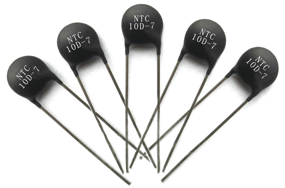
NTC Thermistors
VI Varistors
6.1 Testing Method
Use the gear “Rxlk” of the multimeter to measure the forward and reverse insulation resistance between the two pins of the varistor, and the measured value usually are infinite.
6.2 Testing Experience
If the measured resistance value is not infinite, it indicates there is a leakage current. If the measured resistance value is too small, it means the varistor is damaged and cannot be used.

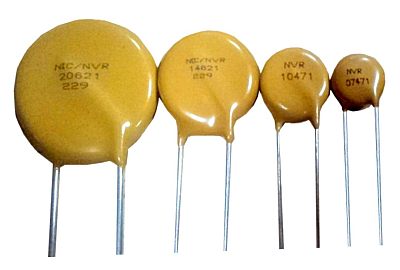
Varistors
VII Photoresistors
7.1 Testing Method
(1) Use a piece of black paper to cover the light-transmitting window of the photoresistor. At this time, the pointer of the multimeter will keep still, and the resistance value is close to infinity.
(2) Aim a light source with the light-transmitting window of the photoresistor. At this time, the pointer of the multimeter will swing with a large amplitude, and the resistance value is significantly reduced.
(3) Aim the light-receiving window of the photoresistor at the incident light, and shake the small black paper on the upper part of the light-shielding window to make it receive the light intermittently. At this time, the pointer of the multimeter should swing left and right with the shaking of the black paper. If the multimeter pointer always stops at a certain position and does not oscillate with the shake, it indicates that the photosensitive material of the photoresistor has been damaged.
7.2 Testing experience
For method (1), the larger the measured value is, the better the performance of the photoresistor is. If the value is too small or close to zero, the photoresistor may has been burned and can no longer be used.
For method (2), the smaller the measured value is, the better the performance of the photoresistor is. If this value is too large, it indicates that the open circuit inside the photoresistor is damaged and cannot be used again.
![]()
A Potentiometer
You May Also Like:
What Are the Functions and Applications of the Varistor?
How to Test Ground Resistance?
What is the giant magnetoresistance (GMR)?
The Pull-up Resistor and Pull-down Resistor
Ordering & Quality
| Photo | Mfr. Part # | Company | Description | Package | Qty |
|
MC145484DW | Company:NXP / Freescale | Remark:IC 5V PCM CODEC-FILTER 20-SOIC W | Package:20-SOIC (0.295", 7.50mm Width) |
MC145484DW Datasheet |
In Stock:38288 Inquiry |
Inquiry |
|
MAX811SEUS-T | Company:Maxim Integrated | Remark:IC MPU V-MONITOR 2.93V SOT143-4 | Package:TO-253-4, TO-253AA |
MAX811SEUS-T Datasheet |
In Stock:33630 Inquiry |
Inquiry |
|
MC68908GZ8MFAE | Company:NXP | Remark:IC MCU 8BIT 8KB FLASH 48LQFP | Package:48-LQFP |
MC68908GZ8MFAE Datasheet |
In Stock:106 Inquiry |
Inquiry |
|
DS2431+ | Company:Maxim Integrated | Remark:IC EEPROM 1KBIT TO92-3 | Package:TO-226-3, TO-92-3 (TO-226AA) |
DS2431+ Datasheet |
In Stock:857278 Inquiry |
Inquiry |
|
MC9S08QD4CSC | Company:NXP | Remark:IC MCU 8BIT 4KB FLASH 8SOIC | Package:SOIC8 |
MC9S08QD4CSC Datasheet |
In Stock:41393 Inquiry |
Inquiry |
|
MAX14515EWA+T | Company:Maxim Integrated | Remark:IC LENS DVR SMALL LIQUID 8-WLP | Package:8-WFBGA, WLCSP |
MAX14515EWA+T Datasheet |
In Stock:9184 Inquiry |
Inquiry |
|
MC9S08GT16CFBE | Company:NXP / Freescale | Remark:IC MCU 8BIT 16KB FLASH 44QFP | Package:44-QFP |
MC9S08GT16CFBE Datasheet |
In Stock:16320 Inquiry |
Inquiry |
|
MC908QB4CDWE | Company:NXP | Remark:IC MCU 8BIT 4KB FLASH 16SOIC | Package:16-SOIC (0.295", 7.50mm Width) |
MC908QB4CDWE Datasheet |
In Stock:3816 Inquiry |
Inquiry |
|
MBRD340G | Company:ON Semiconductor | Remark:DIODE SCHOTTKY 40V 3A DPAK | Package:TO-252-3, DPak (2 Leads + Tab), SC-63 |
MBRD340G Datasheet |
In Stock:604 Inquiry |
Inquiry |
|
MC68332GCEH20 | Company:NXP / Freescale | Remark:IC MCU 32BIT 132PQFP | Package:132-BQFP Bumpered |
MC68332GCEH20 Datasheet |
In Stock:2569 Inquiry |
Inquiry |