28
Introduction
The ground resistance is a resistance that the current flows into the ground from the grounding device and then flows through the earth to another grounding body or diffuses far away. The value of ground resistance reflects the good degree of contact between electrical device and the ground and reflects the scale of grounding grid.
This article mainly introduces how to test the ground resistance with the ground resistance tester. On one hand, it briefly introduces the conception of the ground resistance; on the other hand, it mainly introduce how to test the ground resistance with the ground resistance tester from several aspects.
Catalog
Introduction | |
ⅠConception of the Ground Resistance | |
II Measurement Principle of Ground Resistance | |
III The Common Ways of Testing Ground Resistance | 3.1 Two-point Method |
3.2 Three-point Method | |
3.3 Four-point Method | |
3.4 Clamping Method | |
IV How to Test the Ground Resistance with the Ground Resistance Tester | 4.1 Testing Tool -- Ground resistance Tester |
4.2 Preparations before the Testing | |
4.3 How to Use the Ground Resistance Tester | |
4.4 Notes of the Usage of the Ground Resistance Tester | |
4.5 Technical Requirements for Setting up Ground Resistance Tester | |
4.6 Functions of Ground Resistance Tester | |
4.7 Specifications of Ground Resistance Tester | |
4.8 Common Faults of Ground Resistance Tester and the Corresponding Solutions | |
Ⅰ Conception of the Ground Resistance
Many household appliances, especially large electrical appliances such as refrigerators, washing machines, and air conditioners, use three-core power cords. In fact, the electrical appliances that use the general utility power can work normally as long as there are two zero wires and two fire wires. The extra line is the ground wire, which means that these appliances must be grounded.
The introduction of grounding technology was originally designed to prevent lightning strikes on equipment such as electricity or electronics. The purpose is to introduce the lightning strike current generated by lightning into the earth through a lightning rod so as to protect the buildings. At the same time, grounding is also an effective means to protect personal safety. When the phase line caused by some reason (such as poor wire insulation, aging of the line, etc.) and the equipment casing touch, the casing of the equipment will have dangerous voltage. The generated current will be protected to the ground through the protective ground, thus playing the role of personal safety.
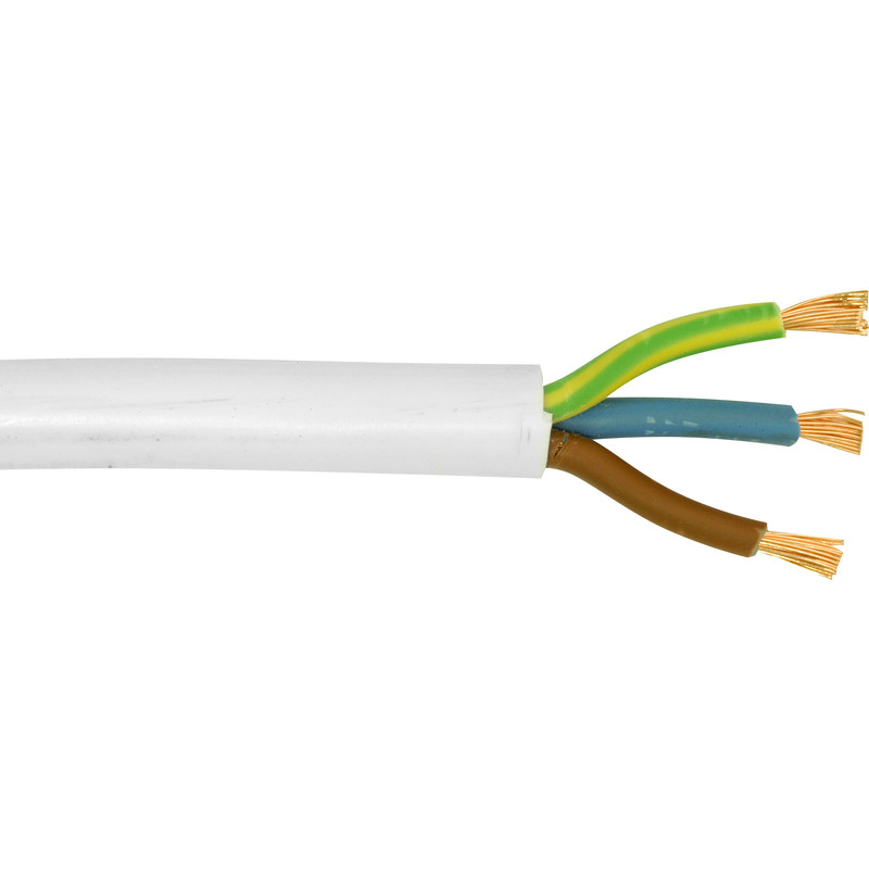
Three-core Power Cords
The ground resistance is an important parameter used to measure whether the grounding state is good. It is the resistance that the current flows from the grounding device into the earth and then flows through the earth to another grounding body or spreads to a distant place. It includes the grounding wire and the grounding body itself. The contact resistance between the resistor, the grounding body and the earth's resistance, and the earth's resistance between the two grounding bodies or the ground resistance of the grounding body to infinity. The magnitude of the ground resistance directly reflects the degree of contact between the electrical device and the "ground" and also reflects the scale of the grounding grid. The concept of ground resistance is only applicable to small grounding grids; as the footprint of the grounding grid increases and the soil resistivity decreases, the inductive component of the grounding impedance becomes more and more important. The large grounding grid should be designed with grounding impedance.
For high-voltage and ultra-high-voltage substations, the concept of “grounding impedance” should be used instead of “ground resistance”. It is also recommended to use contact voltage and step voltage as safety criteria. The portable and accurate inter-frequency measurement system should also be used. The system obtains the correct result of the grounding impedance to ensure the safety of the person and equipment, and is conducive to the safe operation of the power system.
II Measurement Principles of Ground Resistance
2.1 There are many factors affecting the ground resistance, such as the size (length, thickness), shape, quantity, buried depth, surrounding geographical environment (such as flat, ditches, slopes are different), soil moisture, texture, etc., may have an impact on the ground resistance.
2.2 The ground resistance tester we use is a relatively traditional measuring instrument. Its basic principle is to use the three-point voltage drop method. The measurement method is to insert two auxiliary test piles on the one side of the grounding pile (called X), and the two test piles are required to be located on the same side of the ground-tested pile, and the three piles are basically in a straight line. The distance of the auxiliary test pile (called Y) is about 20 meters from the tested pile, and the distance from the tested pile is about 40 meters from the auxiliary test pile (called Z).
III The Common ways of Testing Ground Resistance
3.1 Two-point Method
With this method, the resistance of a series of two electrodes is measured by connecting the P1 and C1 terminals to the ground electrode to be tested. P2 and C2 are connected to separate all-metal grounding points (such as water pipes or building steel).
The two-point method is the easiest way to obtain a ground resistance reading, but it is not as accurate as the three-point method and can only be used as a last resort. It is most effective for quickly testing the connections and conductors between the connection points.
Note: the measured grounding electrode must be far enough away from the auxiliary contact to exceed its impact range.
3.2 Three-point Method
The three-point method is the most thorough and reliable test method; it is used to measure the ground resistance of the grounded electrode. Using a four-terminal tester, the P1 and C1 terminals on the instrument are jumpered and connected to the ground electrode under test, while the C2 reference rod is driven directly away into the ground as far as possible away from the electrode under test. Then, the potential reference point P2 is driven into the earth by a certain number of points, approximately on a straight line between C1 and C2. Record the resistance reading for each P2 point.
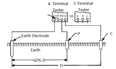
Potential test methods
The measured value is plotted on the curve of resistance and distance. Read the correct ground resistance from the curve, which is approximately 62% of the total distance between C1 and C2. There are three basic types of potential decline methods:
(1) Complete potential drop: many tests are different spaces of P and draw a complete resistance curve.
(2) Simplified potential drop: three measurements are taken at a defined distance of P and mathematical calculations are used to determine the resistance.
(3) 61.8 Rule: use P for a single measurement, with a distance of 61.8% (62%) of the distance between C1 and C2.
3.3 Four-point Method
This method is the most commonly used method for measuring soil resistivity, which is important for designing electrical grounding systems. In this method, four small-sized electrodes are driven into the earth at the same depth and an equal distance (straight line) and measured.
The moisture and salt content of the soil fundamentally affects its electrical resistivity. Soil resistivity measurements are also affected by existing grounding electrodes. If the buried conductive object in contact with the soil is close enough to change the test current mode, the reading will be invalid. This is especially true for large or long objects.
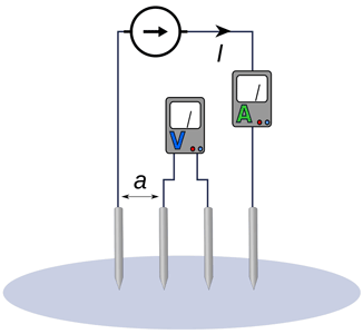
As shown in the figure above, the four-needle method is the most commonly used technique for soil resistivity measurement.
3.4 Clamping Method
The clamping method is unique in that it measures the resistance without disconnecting the ground system. It is fast and easy, and also includes grounding and overall ground connection resistance in the measurement.
By "clamping" the tester around the measured grounding electrode, it is similar to the method of measuring current with multimeter current clamp.The tester applies a known voltage through the transmit coil without the need for a direct electrical connection and measures the current through the receive coil. This test is performed at a high frequency to make the transformer as small and practical as possible.
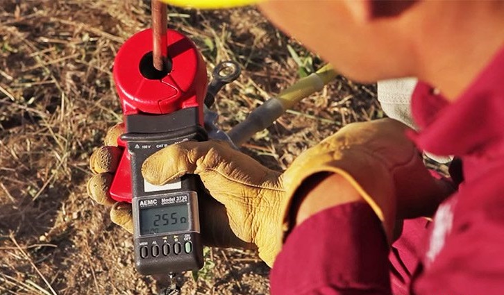
Some limitations of the clamping method
(1) Only valid if there are multiple parallel connections.
(2) Cannot be used on isolated ground, not suitable for installation inspection or debugging new sites.
(3) If there is an alternative low resistance loop that does not involve soil, such as a cellular tower or substation, this method cannot be used.
IV How to Test the Ground Resistance with the Ground Resistance Tester
4.1 Testing Tool -- Ground Resistance Tester
The ground resistance tester is a common instrument for testing and measuring the ground resistance. It is also an indispensable tool for the electrical safety inspection and acceptance of grounding project completion. In recent years, due to the rapid development of computer technology, the ground resistance tester has also penetrated a large number of microprocessor technology. Its measurement function, content and accuracy are better than the general instrument. At present, the ground resistance tester can meet all the requirements of grounding measurement. With the new champ method, the on-line direct measurement is not necessary for piling and laying-out. A powerful ground resistance tester is controlled by a microprocessor, which can automatically detect the connection status of each interface and the interference voltage and interference frequency of the ground network. It also has unique functions such as numerical retention and intelligent prompting.
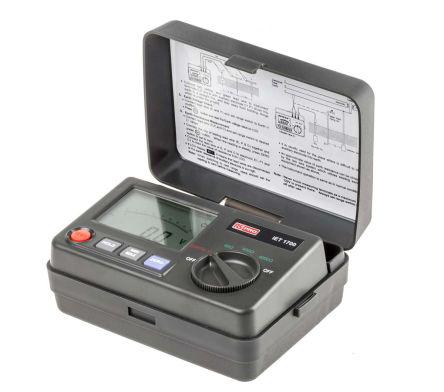
Clamp-on ground resistance tester is a major breakthrough in traditional ground resistance measurement technology, widely used in ground resistance measurement of electric power, telecommunications, meteorology, oilfield, construction and industrial electrical equipment. It does not need to disconnect the grounding down conductor when measuring the grounding system with loop. It is safe, fast and easy to use. It can measure the ground fault that cannot be measured by the conventional method, and can be applied to the case where the conventional method cannot measure, because it measures the combined value of the grounding body resistance and the grounding lead resistance. It can be divided into a long jaw and a round jaw. The long jaw is especially suitable for the case where the flat steel is grounded.
4.2 Preparations before the Testing
(1) Read the instructions of the ground resistance tester to fully understand the structure, performance and usage of the tester.
(2) Prepare the necessary tools and all instrument accessories for the measurement, and wipe the tester and grounding probe cleanly. Especially the grounding probe, the dirt and rust which affect the conductivity of the surface must be cleaned up.
(3) Disconnect the grounding trunk from the connection point of the grounding body or from the connection points of all grounding branches, so that the grounding body is separated from any connection and becomes an independent body.
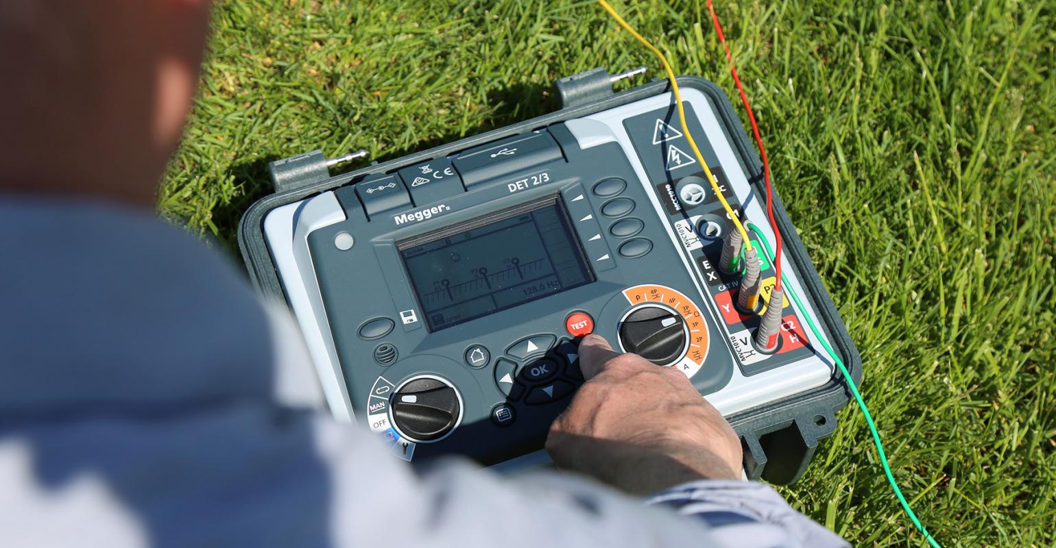
4.3 How to Use the Ground Resistance Tester
(1) Connect the test line: connect the test line as shown in the figure below (the thick line is connected to the current output port, and the thin line is connected to the resistance detection port).
(2) Turn on the tester, press the power switch, and preheat for 5 minutes.
(3) Select the test range switch as required, generally choose 600mΩ file.
(4) Turn the current knob counterclockwise to the zero position, and then short-circuit the two groups of test clamps.
(5) Select a manual test or a timing test according as needed (the time switch is “off” for manual test and “on” for automatic timing test).
(6) After the condition is set correctly, press the “Start” button, test the light, and adjust the “Current Adjustment” knob to the selected current value (generally 12A).
(7) Set the “Preset/Test” switch in the “Preset” state and adjust the “Alarm Resistance Adjustment” potentiometer. The preset alarm resistance value is 500mΩ. (The alarm resistance value can be preset only if there is a current output).
(8) After the preset alarm resistance is adjusted, press the “Reset” button to cut off the output current, and at the same time, turn the “Current Adjustment” knob to the minimum to separate the shorted test clamps.
(9) Spot check before test: short-circuit the test clamp, adjust the current knob to 5A current value, disconnect the test clamp, the tester will issue an alarm and the spot checking is qualified, otherwise it is not qualified.
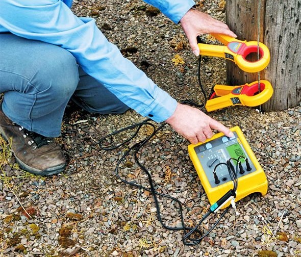
After the tester passes the spot checking, enter the test: first connect the test clamp to the metal part of the lamp housing and the grounding wire connection point, then press the “Start” button, the “Test” light is on, and adjust the “Current adjustment knob” to the required current value. Read down the resistance values on the display screen. During the test, when the ground resistance of the tested object is greater than the value of the set alarm(500mΩ), the tester will issue an intermittent sound and light alarm. At this time, it is determined that the ground resistance of the tested lamp is unqualified. If you need to stop the test, press the "Reset" button (the tester automatically cuts off the power supply when it is in the timing test). When the "Test" indicator lights out, the circuit current will be cut off. Then remove the test clamp from the tested object for the next measurement.
(10) If you need to continue measuring the same product, please repeat step 9 If you need to test other products, please repeat step 3 to 9 Please turn off the tester if there is no measurement.
4.4 Notes of the Usage of the Ground Resistance Tester
(1) The grounding line should be disconnected from the protected device to ensure the accuracy of the measurement results.
(2) There should be no stray currents and polarized soil near the measured pole.
(3) It cannot be measured when the soil absorbs too much water after rain, and when the climate, temperature and pressure change dramatically.
(4) The probe should be far away from large metal bodies such as underground pipes, cables, railways, etc. The current pole should be far from more than 10 meters, and the voltage pole should be far from more than 50 meters. If the metal bodies are not connected to the grounding grid, the distance can be shortened by 1/2~1. /3.
(5) Use a well-insulated wire for the connection to avoid leakage.
(6) Pay attention to that the current pole is inserted into the soil so that the ground rod is at a zero-potential state.
(7) The test should be carried out when the soil resistivity is high, such as in the early winter or in the dry summer season.
(8) There should be no electrolytes and decaying corpses in the test site to avoid illusion.
(9) When the galvanometer sensitivity is too high, the potential probe voltage pole can be inserted into the soil shallower. When the galvanometer sensitivity is not enough, water can be injected along the probe to make it wet.
(10) Check the accuracy of the tester at any time.
(11) When using, handling and storing the tester, strong vibration should be avoided.
4.5 Technical Requirements for Setting up Ground Resistance Tester
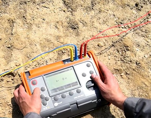
(1) The ground resistance tester should be placed at 1-3 m away from the test point, and should be stable and easy to operate.
(2) Each pin must be in good contact and securely connected.
(3) The two grounding pins should be placed at a distance of 20m and 40m from the left and right sides of the grounding body to be tested. If the two pins are connected by a straight line, the grounding body to be tested should be basically on this line.
(4) Other conductors shall not be used to replace 5, 20 and 40 m long pure copper conductors equipped with instruments.
(5) If the ground resistance tester is centered, the angle between the two pins and the tester should be at least 120°, and it should not be set in the same direction.
(6) The two pins should be placed in the solid soil, and cannot placed in mud, backfill, tress roots, grass, etc.
(7) The test can not be carried out until seven consecutive sunny days after rain.
(8) The grounding body to be tested should be rusted first to ensure reliable electrical connection.
4.6 Functions of Ground Resistance Tester
(1) Accurately measure grounding impedance, ground resistance and grounding reactance of the large grounding grid.
(2) Accurately measure the surface potential gradient of a large grounding grid area.
(3) Accurately measure contact potential difference, contact voltage, step potential difference and step voltage of the large grounding grid
(4) Accurately measure the transfer potential of the large grounding grid;
(5) Measure the soil resistivity.
4.7 Specifications of Ground Resistance Tester
(1) Conditions
● Ambient temperature: 0℃~45℃
● Relative humidity: ≤85%RH
(2) Measurement Range and Constant Current Value (RMS)
● Resistance value: 0~2Ω(10mA),2~20Ω(10mA),20~200Ω(1mA)
● Voltage: AC 0~20V
(3) Measurement accuracy and resolution
● Accuracy: 0~0.2Ω≤±3%±1d,0.2Ω~200Ω≤±1.5%±1d,1~20V≤±3%±1d
● Resolution: 0.001Ω、0.01Ω、0.1Ω、0.01V
(4) Power Supply and Power Consumption
● Maximum power loss: ≤2W
● DC: 8×1.5V(AA,R6) battery
● AC: 220V/50Hz
(5) Volume and weight
● Volume and weight
● Weight: ≤1.4kg
4.8 Common Faults of Ground Resistance Tester and the Corresponding Solutions
Common Fault 1: when the battery voltage is normal and the ground resistance is measured, the measured data is not accurate and the error is large.
Cause: this fault is usually caused by the fault of detection signal filtering and modulation circuit. The common cause is the damage of filter inductance T1.
Solution: replace the filter inductance T1.
Common Fault 2: It was found that the battery voltage was normal, but the ground resistance could not be measured.
Cause: this fault is usually caused by the faults of switching power supply, AC/DC conversion of power dynamometer and constant current output part.
Solution: measure the C-port with a frequency meter. If there is no 820Hz AC output, gradually check the part of the circuit, find the fault part from the output transformer, switch tube, oscillation circuit, etc., and then replace the new parts to repair.

Handy Power Dynamometer
Common Fault 3: the head pointer of the ground resistance tester does not move, or the head pointer of the battery voltage and ground resistance tester does not move when measuring.
Cause: this may be caused by a burnout of the meter or disconnection of the connection between the meter and the circuit board. This is also due to excessive vibration of the ground resistance tester during use or transportation.
Solution: firstly, open the head panel and move the pointer by hand. If the pointer can not return to zero automatically, it indicates that the meter has been damaged. Otherwise, the head should be welded and the meter should be measured with a multimeter resistance. If the circuit is open, it means the meter has been burned out. Then use the multimeter current and voltage file to measure the original connection header connector, press the ground resistance meter to check the voltage button. If the multimeter has a voltage indication, it indicates that the fault of the ground resistance tester is caused by the damage of the meter. After replacing the new meter, it can be repaired. If the meter head is in good condition, then open the shell of the ground resistance tester and check the connection of the meter head. If it is disconnected, it will be OK to connect it again.
You May Also Like:
How to Test Different Kinds of Resistors with a Pointer Multimeter
What Are the Functions and Applications of the Varistor?
What is the giant magnetoresistance (GMR)?
The Pull-up Resistor and Pull-down Resistor
Ordering & Quality
| Photo | Mfr. Part # | Company | Description | Package | Qty |
|
MBRD340G | Company:ON Semiconductor | Remark:DIODE SCHOTTKY 40V 3A DPAK | Package:TO-252-3, DPak (2 Leads + Tab), SC-63 |
MBRD340G Datasheet |
In Stock:604 Inquiry |
Inquiry |
|
MRF373ALR1 | Company:FREESCALE | Remark:RF Mosfet LDMOS 32V 200mA 860MHz 18.2dB 75W NI-360 | Package:TO-63 |
MRF373ALR1 Datasheet |
In Stock:85 Inquiry |
Inquiry |
|
MMA2204KEGR2 | Company:Freescale Semiconductor - NXP | Remark:ACCELEROMETER 112.5G ANAL 16SOIC | Package:16-SOIC (0.295", 7.50mm Width) |
MMA2204KEGR2 Datasheet |
In Stock:1330 Inquiry |
Inquiry |
|
H5PS5162FFK-E3C | Company:HYNIX | Remark: | Package:BGA |
H5PS5162FFK-E3C Datasheet |
In Stock:20200 Inquiry |
Inquiry |
|
MC145484DW | Company:NXP / Freescale | Remark:IC 5V PCM CODEC-FILTER 20-SOIC W | Package:20-SOIC (0.295", 7.50mm Width) |
MC145484DW Datasheet |
In Stock:38288 Inquiry |
Inquiry |
|
MCIMX31LCVKN5D | Company:NXP / Freescale | Remark:IC MPU I.MX31 532MHZ 457MAPBGA | Package:457-LFBGA |
MCIMX31LCVKN5D Datasheet |
In Stock:147 Inquiry |
Inquiry |
|
AGLN060V5-CSG81 | Company:Microsemi Corporation | Remark:IC FPGA 60 I/O 81CSP | Package:81-WFBGA, CSBGA |
AGLN060V5-CSG81 Datasheet |
In Stock:130 Inquiry |
Inquiry |
|
BAT54HT1G | Company:ON Semiconductor | Remark:DIODE SCHOTTKY 30V 200MA SOD323 | Package:SOD323 |
BAT54HT1G Datasheet |
In Stock:995379 Inquiry |
Inquiry |
|
MC908QB4CDWE | Company:NXP | Remark:IC MCU 8BIT 4KB FLASH 16SOIC | Package:16-SOIC (0.295", 7.50mm Width) |
MC908QB4CDWE Datasheet |
In Stock:3816 Inquiry |
Inquiry |
|
TMS320DM8127SCYED3 | Company:Texas Instruments | Remark:IC DGTL MEDIA PROCESSOR | Package:684-BFBGA, FCBGA |
TMS320DM8127SCYED3 Datasheet |
In Stock:433 Inquiry |
Inquiry |