7
Introduction
Varistor, a resistive device with non-linear volt-ampere characteristics, which is mainly used to clamp a voltage and absorb excess current to protect the sensitive devices when the circuit is under overvoltage. Its English name is "Voltage Dependent Resistor" abbreviated as "VDR". Its resistor material is semiconductor, so it is a kind of semiconductor resistor.
Varistor is a voltage-limiting protection device. Using the non-linear characteristics of the varistor, when an overvoltage occurs between the two poles of the varistor, the varistor can clamp the voltage to a relatively fixed voltage value, thus realizing the protection of the later circuit.
This article is going to introduce the varistor comprehensively from its functions, applications, parameters and so on.
Catalog
Introduction | |
I Structural Characteristics of Varistor | |
II Basic Performance of Varistor | 2.1 Protection Characteristics |
2.2 Shock Resistance | |
2.3 Life Characteristics | |
III Parameters of Varistor | |
IV Types of Varistor | 4.1 Classified by Layout |
4.2 Classified by Application Materials | |
4.3 Classified by Volt-ampere Characteristics | |
V Selections of Varistors | 5.1 Selection of Varistor Voltage V1mA |
5.2 Selection of Flow Rate | |
5.3 Selection of Clamping Voltage | |
5.4 Selection of CP | |
5.5 Resistance Match | |
VI Calculation of Varistor Voltage | 6.1 Generally Calculated with U1mA=KUac |
6.2 Calculation of Nominal Discharge Current | |
6.3 Parallel Connection of Varistors | |
VII Functions of Varistor | |
VIII Main Applications of Varistors | 8.1 Lightning Protection |
8.2 Circuit Protection | |
8.3 Switch Protection | |
8.4 Device Protection | |
I Structural Characteristics of Varistor
Unlike ordinary resistors, varistors are made based on the non-linear characteristics of semiconductor materials.
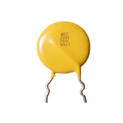
Figure 1. is the shape of varistor, and its internal structure is shown in Figure 2.
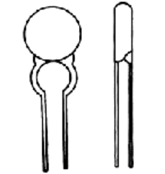
Figure 1.
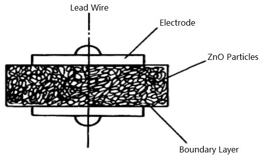
Figure 2.
Ordinary resistors obey Ohm's law, while the voltage and current of the varistor have a special non-linear relationship. When the voltage at both ends of the varistor is lower than the nominal rated voltage, the resistance value of the varistor is close to infinite, and there is almost no current flowing through the inside of the varistor. When the voltage at both ends of the varistor is slightly higher than the nominal rated voltage, the varistor will break down and turn on rapidly, and the working current will increase sharply from the high impedance state to the low impedance state. When the voltage at both ends is lower than the nominal rated voltage, the varistor can be return to a high impedance state. When the voltage at both ends of the varistor exceeds its maximum limit voltage, the varistor will break down completely and will not recover.
The figure below shows a typical application circuit for a varistor.
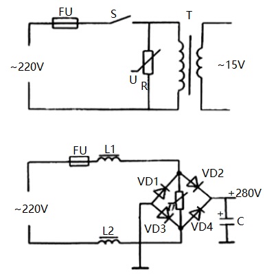
Typical Application Circuit for a Varistor
II Basic Characteristics of Varistor
2.1 Protection Characteristics
When the shock intensity (or impulse current Isp=Usp/Zs) of the impact source does not exceed the specified value, the limiting voltage of the varistor shall not exceed the impulse withstand voltage (Urp) of the protected object.
2.2 Shock Resistance
The varistor itself should be able to withstand the specified impact current, impact energy, and the average power when multiple shocks occur one after another.
2.3 Life Characteristics
One is the continuous working voltage life, that is, the varistor should be able to work reliably for a specified time (hours) under the specified ambient temperature and system voltage conditions; another is the impact life, that is, the number of times that the specified impact can be reliably withstood.
2.4 After the varistor is involved in the system, besides playing the protective role of the "safety valve", it will bring some additional effects, which is called the "secondary effect". It should not reduce the normal working performance of the system. There are three main factors to be considered at this time. One is the capacitance of the varistor itself (tens to tens of thousands of PF), the second is the leakage current at the system voltage, and the third is the influence of the non-linear current of varistor on other circuits through the coupling of source impedance.
III Parameters of Varistor
The main parameters of the varistor are nominal voltage, voltage ratio, maximum control voltage, residual voltage ratio, discharge current capacity, leakage current, voltage temperature coefficient, current temperature coefficient, voltage nonlinear coefficient, insulation resistance, static capacitance and so on.
3.1 Nominal Aristor Voltage
MYG05K stipulates that the passing current is 0.1mA, MYG07K, MYG10K, MYG14K and MYG20, and the nominal voltage refers to the voltage at both ends of varistor when passing through 1mA DC current.
3.2 Maximum Permissible Voltage
This voltage is divided into AC and DC. If it is AC, it refers to the effective value of the AC voltage allowed by the varistor, which is expressed in ACrms. Therefore, the varistor with the maximum allowable voltage should be selected under the effective value of the AC voltage. In the AC circuits, there should be: min (U1mA) ≥ (2.2 ~ 2.5) Uac, and the “Uac” is the effective value of AC operating voltage in the circuit. In the DC circuits, there should be: min (U1mA) ≥ (1.6) Udc, and the “Udc” is the rated DC operating voltage in the circuit. The above principles is mainly to ensure that the varistor has an appropriate safety margin when it is applied in the power supply circuit.
3.3 Discharge Current Capacity
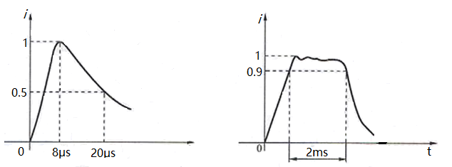
It refers to the maximum pulse (peak) current value allowed to pass through the varistor under specified conditions (imposing a standard impulse current at specified time intervals and number of time). Generally, overvoltage is a pulse or a series of pulses. There are two kinds of shock waves used in the experimental varistor, one is 8/20μs wave, that is the pulse wave with 8μs wave head and 20μs wave tail time, and the other is a square wave of 2ms, as shown in the following figure:
3.4 Maximum Limited Voltage
It refers to the maximum voltage that can be withstood at both ends of a varistor and represents the voltage generated at both ends when the specified impulse current Ip passes through the varistor.
3.5 Maximum Energy (energy tolerance)
The energy absorbed by varistors is usually calculated in the following formula
W=kIVT(J)
I——Peak value flowing through the varistor
V—— Voltage at both ends of varistor when current I flows through varistor
T——Current duration
k——Waveform factor of current I
2ms square wave k=1
8/20μs wave k=1.4
10/1000μs wave k=1.4
When 2ms square wave, the varistor absorbs energy up to 330J per square centimeter; when 8/20μs wave, the current density can reach 2000A per cubic centimeter, which indicates that its flow capacity and energy tolerance are very large.
In general, the larger the chip diameter of the varistor is, the greater its energy tolerance is and the greater its withstand current is. When using varistors, we should also consider the overvoltage which often encounters smaller energy but higher frequency, such as dozens of seconds, one or two minutes of overvoltage. At this time, we should consider the average power that the varistors can absorb.
3.6 Voltage Ratio
It is the ratio of the voltage value generated when the varistor current is 1 mA to the voltage value generated when the varistor current is 0.1 mA.
3.7 Rated Power
The maximum power that can be consumed at a specified ambient temperature.
3.8 Maximum Peak Current
One time: the maximum current value of the current with a standard waveform of 8/20μs, and the rate of change of the varistor voltage is still within ±10%. 2 times: The maximum current value of the double impact with the current of the standard waveform of 8/20 μs. The time interval between the two shocks is 5 minutes, at which time the rate of change of the varistor voltage is still within ±10%.
3.9 Residual Voltage Ratio
When the current flowing through the varistor is at a certain value, the voltage generated at both ends of the varistor is called residual voltage. The residual voltage ratio refers to the ratio of the residual voltage to the nominal voltage.
3.10 Leakage Current
Leakage current, also known as waiting current, refers to the current flowing through the varistor at a specified temperature and maximum DC voltage.
3.11 Voltage Temperature Coefficient
The voltage temperature coefficient refers to the rate of change of the nominal voltage of the varistor in the specified temperature range (20~70℃). That is, the relative change of the two ends of varistor when the current through the varistor remains constant and the temperature changes by 1℃.
3.12 Current Temperature Coefficient
It refers to the relative change of current flowing through the varistor when the voltage at both ends of varistor remains constant and the temperature changes by 1℃.
![]()
3.13 Voltage Nonlinear Coefficient
It refers to the ratio of the static resistance value to the dynamic resistance value of a varistor under a given applied voltage.
3.14 Insulation Resistance
It refers to the resistance value between the lead wire (pin) of the varistor and the insulating surface of the resistor.
3.15 Static Capacitance
It refers to the inherent capacitance of varistor itself.
IV Types of Varistor
Varistors can be classified according to layout, manufacturing process, application materials and volt-ampere characteristics.
4.1 Classified by Layout
It can be divided into junction varistor, bulk varistor, single particle layer varistor, thin film varistor and so on.
4.2 Classified by Application Materials
It can be divided into zinc oxide varistor, silicon carbide varistor, metal oxide varistor, germanium (silicon) varistor, barium ferrite varistor and so on.
4.3 Classified by Volt-ampere Characteristics
It can be divided into symmetrical varistor (without polarity) and asymmetrical varistor (with polarity).
V Selections of Varistors
When selecting a varistor, the specific conditions of the circuit must be considered. Generally, the following principles should be followed.
5.1 Selection of Varistor Voltage V1mA
According to the power supply voltage, the power supply voltage continuously applied across the varistor cannot exceed the “maximum continuous operating voltage” value listed in the specification. That is, the maximum DC working voltage of the varistor must be greater than the DC working voltage VIN of the power line (signal line) which is VDC ≥ VIN; for the varistor selection of the 220V AC power supply, it is necessary to give full consideration to the fluctuation range of the working voltage of the power grid, and to select the varistor voltage value of the varistor, there should be enough allowance for the selection of the varistor. The general fluctuation of the domestic power grid is 25%. A varistor with the voltage of 470V to 620V should be selected. Selecting a varistor with a higher voltage can reduce the failure rate and prolong the service life, but the residual voltage is slightly increased.
5.2 Selection of Flow Rate
The nominal discharge current of the varistor should be greater than the surge current required to withstand or the maximum surge current that may occur during operation of the equipment. The nominal discharge current should be calculated according to the value of more than 10 shocks in the surge life curve of varistor, which is about 30% (0.3IP) of the maximum impulse flow rate.
5.3 Selection of Clamping Voltage
The clamp voltage of the varistor must be smaller than the maximum voltage (safe voltage) that the protected component or device can withstand.
5.4 Selection of CP
For high frequency transmission signals, the Cp should be smaller, and vice versa.
5.5 Resistance Match
The relationship between the internal resistance R(R≥2Ω) of the protected component (circuit) and the transient internal resistance Rv of varistor: R≥5R. For protected components with small internal resistance, use large-capacitance varistor as much as possible without affecting the signal transmission rate.
VI Calculation of Varistor Voltage
6.1 Generally Calculated with U1mA=KUac
In U1mA=KUac, K is the coefficient related to power quality. Generally, K=(2~3), the cities with better power quality can take smaller ones, and the rural areas with poor power quality (especially in mountainous areas) should take bigger ones; Uac is the RMS of AC power supply voltage. For 220V-240V AC power supply lightning arrester, the varistor with the voltage of 470V-620V is suitable. Selecting a varistor with a higher voltage can reduce the failure rate and prolong the service life, but the residual voltage is slightly increased.
General Calculation of Varistor Voltage
6.2 Calculation of Nominal Discharge Current
The nominal discharge current of the varistor should be greater than the surge current required to withstand or the maximum surge current that may occur during operation of the equipment. The nominal discharge current should be calculated according to the value of more than 10 shocks in the surge life curve of varistor, which is about 30% (0.3IP) of the maximum impulse flow rate.
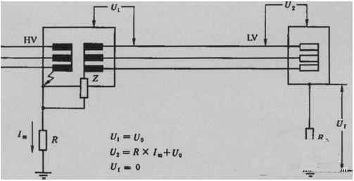
Calculation of Nominal Discharge Current
6.3 Parallel Connection of Varistors
When a varistor does not meet the requirements of the nominal discharge current, multiple varistor should be used in parallel. Sometimes, in order to reduce the limiting voltage and make the nominal discharge current meet the requirements, multiple varistors are also used in parallel. It is important to note that when the varistors are used in parallel, it is necessary to strictly select the parameters(such as ΔU1mA≤3V,Δα≤3) for matching, so as to ensure uniform distribution of current.
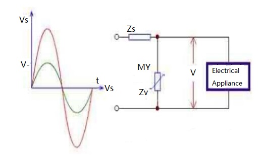
Parallel Connection of Varistors
VII Functions of Varistor
The greatest characteristic of varistor is that when the voltage applied on it is lower than its threshold value "UN", the current flowing through it is extremely small, which is equivalent to a closed valve. When the voltage exceeds UN, its resistance value decreases, which makes the current flowing through it surge and has little effect on other circuits, thus reducing the influence of overvoltage on subsequent sensitive circuits. With this function, it is possible to suppress abnormal overvoltages that often occur in circuits and protect circuits from overvoltages.
The protection function of varistor has been widely used. For example, the power circuit of home TVs uses varistor to complete the overvoltage protection function. When the voltage exceeds the threshold value, the varistor reflects its clamping characteristic, lowers the over-high voltage, and makes the post-stage circuit operate within the safe voltage range.
Varistors are mainly used for transient over-voltage protection in circuits, but because of their similar volt-ampere characteristics to semiconductor regulators, they also have a variety of circuit component functions. For example, the varistor is a kind of DC high voltage and small current regulatort, and the stable voltage can reach thousands of volts, which is beyond the reach of silicon regulator; the varistor can be used as a voltage fluctuation detecting component; can be used as the DC level shift element; can be used as a fluorescent starting element; can be used as a voltage equalizing element.
VIII Main Applications of Varistors
8.1 Lightning Protection
Lightning strikes can cause atmospheric overvoltages, which mostly belongs to inductive overvoltage. The overvoltage generated by the lightning strike on the transmission line is called the direct lightning overvoltage, and its voltage value is particularly high, which can cause great harm with voltage of 102~104V. Therefore, for outdoor power systems and electrical equipment, measures must be taken to prevent overvoltage. The use of ZnO varistor arresters is very effective in eliminating atmospheric overvoltages. Generally, it is connected in parallel with electrical equipment. If the electrical equipment requires a low residual voltage, multilevel protection can be used.
The following are several common protection circuits that use ZnO arresters to eliminate atmospheric overvoltages: fig. (a) is the connection method of the ZnO arrester for three-phase electrical equipment, fig. (b) is the connection method of the ZnO arrester for the solenoid valve control system, and fig. (c) is the connection method of the ZnO arrester between the power supply and the load.
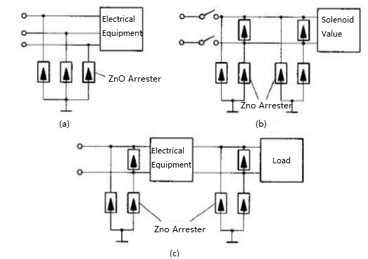
Lightning Protection
8.3 Switch Protection
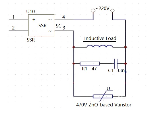
When a circuit with an inductive load is suddenly disconnected, its overvoltage can exceed several times of the power supply voltage. Overvoltage can cause arcing and spark discharge between contacts, which can damage contacts such as contactors, relays and electromagnetic clutches, and shorten the service life of the device. The varistor has a shunt at high voltages, so it can be used to protect the contacts by preventing spark discharges at the moment of contact break. The connection method of the varistor protection switch or contact is shown in the figure below. When the varistor is connected in parallel with the inductor, the dry voltage of the switch and the dry voltage of the varistor are the sum of the residual voltage of the varistor. The energy absorbed by the varistor is the energy stored by the inductor. When the varistor is connected in parallel with the switch, the overvoltage on the switch is equal to the residual voltage of the varistor, and the energy absorbed by the varistor is slightly larger than the energy stored in the inductor.

Switch Protection
8.4 Device Protection
In order to prevent the semiconductor devices from being burnt due to overvoltage generated for some reasons, varistors are often used to protect them. The figure below shows the application circuit of the varistor protection transistor. The damage of the overvoltage to the transistor can be effectively suppressed between the collector and the emitter of the transistor or the primary shunt varistor of the transformer. Under normal voltage, the varistor is in a high impedance state with minimal leakage current. When subjected to an overvoltage, the varistor quickly changes to a low impedance state, and the overvoltage energy is absorbed by the varistor in the form of a discharge current. After the surge voltage is passed, when the circuit or component is subjected to a normal voltage, the varistor returns to a high impedance state.

Device Protection
You May Also Like:
How to Test Different Kinds of Resistors with a Pointer Multimeter?
How to Test Ground Resistance?
What is the giant magnetoresistance (GMR)?
The Pull-up Resistor and Pull-down Resistor
Ordering & Quality
| Photo | Mfr. Part # | Company | Description | Package | Qty |
|
MMB02070C2201FB200 | Company:VISHAY | Remark:RES SMD 2.2K OHM 1% 1W 0207 | Package:SMD |
MMB02070C2201FB200 Datasheet |
In Stock:63360 Inquiry |
Inquiry |
|
D2TO035CR0500FTE3 | Company:Vishay Sfernice | Remark:RES SMD 0.05 OHM 1% 35W TO263 | Package:TO-263-3, D²Pak (2 Leads + Tab), TO-263AB |
D2TO035CR0500FTE3 Datasheet |
In Stock:70 Inquiry |
Inquiry |
|
MC9S12XDG128MAA | Company:NXP | Remark:IC MCU 16BIT 128KB FLASH 80QFP | Package:80-QFP |
MC9S12XDG128MAA Datasheet |
In Stock:126 Inquiry |
Inquiry |
|
SLB 9635 TT1.2 FW3.17 | Company:Infineon Technologies | Remark:IC SPECIALIZED | Package: |
SLB 9635 TT1.2 FW3.17 Datasheet |
In Stock:10854 Inquiry |
Inquiry |
|
K9F4G08UOA-P1BO | Company:SAMSUNG | Remark:4G-bit NAND Flash Memory with spare 128M-bit | Package: |
K9F4G08UOA-P1BO Datasheet |
In Stock:5960 Inquiry |
Inquiry |
|
MC9S12DG256MPVE | Company:NXP / Freescale | Remark:IC MCU 16BIT 256KB FLASH 112LQFP | Package:112-LQFP |
MC9S12DG256MPVE Datasheet |
In Stock:634 Inquiry |
Inquiry |
|
ICE65L04F-TCS63I | Company:Lattice | Remark:IC FPGA 48 I/O 63WLCSP | Package:BGA63 |
ICE65L04F-TCS63I Datasheet |
In Stock:5759 Inquiry |
Inquiry |
|
DSPB56374AE | Company:NXP / Freescale | Remark:IC DSP 24BIT 150MHZ 52-LQFP | Package:52-LQFP |
DSPB56374AE Datasheet |
In Stock:10211 Inquiry |
Inquiry |
|
MC14600P | Company:Freescale Semiconductor - NXP | Remark:IC ALARM GENERAL MONO 16-DIP | Package:16-DIP (0.300", 7.62mm) |
MC14600P Datasheet |
In Stock:1177 Inquiry |
Inquiry |
|
LFE2-6SE-5FN256C | Company:Lattice Semiconductor | Remark:IC FPGA 190 I/O 256BGA | Package:256-BGA |
LFE2-6SE-5FN256C Datasheet |
In Stock:270 Inquiry |
Inquiry |