12
When designing boards, we tend to pay attention to those parts that seem to be more core and more critical. They may not pay enough attention to those unimportant parts, but these places often bring catastrophic consequences.
For example, the power-on time and sequence of the power supply, we need to pay attention to the rise time of the system power supply. Many people don't understand why it is necessary to set a rise time for power-on? I tell you, the problem is great if we do not deal well here.
Here is an example:
Many simple MCU products use the following methods to do Reset, is that right? Of course, then why? Because so many products have done this, and have not heard of any problems, so it's OK.
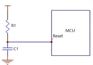
Today we will use the easiest way to describe whether this will be a problem.
First, let's look at what happens to the power-on reset under ideal conditions:
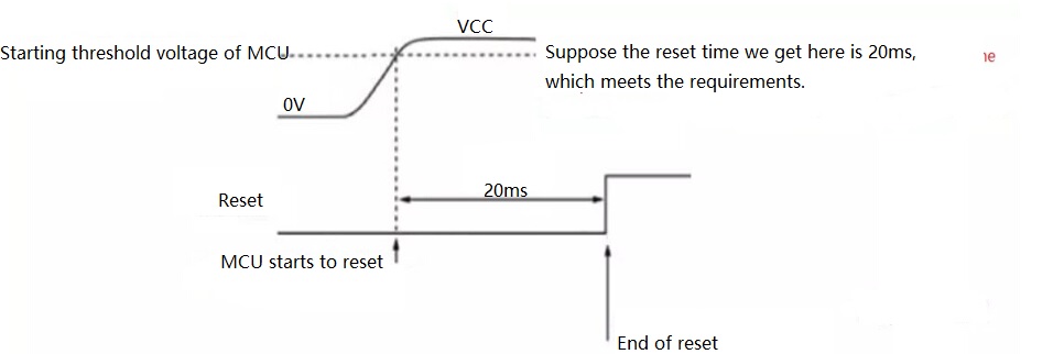
When VCC reaches the working voltage threshold of the MCU, the MCU starts to work, and the reset signal is pulled high after 20ms, Perfect! The problem is that there is always a distance between reality and ideal. Let's first look at what kind of waveform will be obtained by using the reset method of RC charging in the above figure:
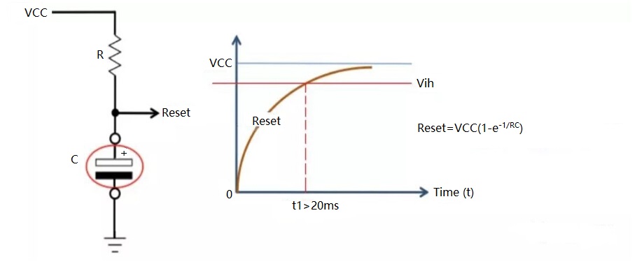
We can see that even when the VCC is powered up perfectly, we also need to make sure that when the Reset is charged to Vih, the time is more than 20ms, but is this really true?
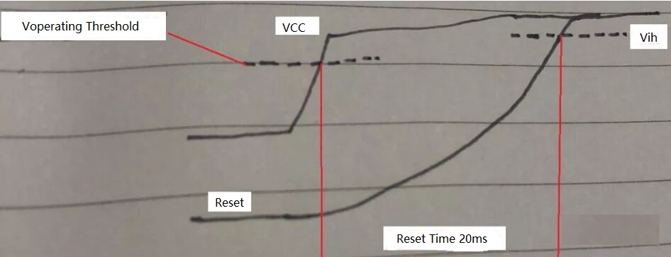
Unfortunately, there is still a little distance between the ideal and the reality. Please look at the above picture. From the VCC power-on to the working voltage threshold, to the reset slowly charges to reach Vih, this period is the reset time we need, but this situation is actually very fragile. What if there is a step or barb when VCC rises? Haha, then the first question has appeared:
1. The Reset Time Becomes Shorter
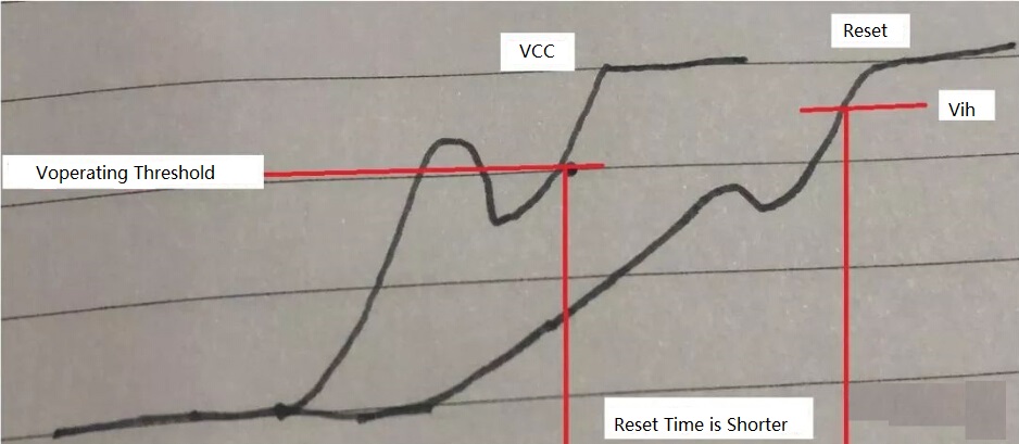
We can see that when the VCC powers up to the threshold voltage for the first time, the chip has started to work, that is, it starts to reset, but the power supply does not live up to expectations, and it falls back below the threshold, so the reset time can only be calculated from the second rise of VCC to the threshold voltage .
Then it can be clearly seen that the reset time becomes shorter. Because each chip has a requirement for the reset time, so if the reset time is not enough, the result is that each power-on is different. Sometimes up, and sometimes not up, and the situation may be even worse when you test it under the low temperature.
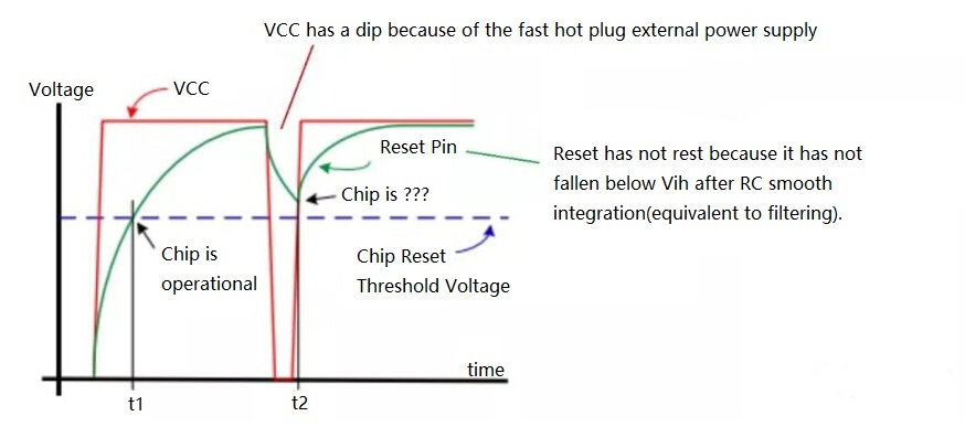
2. Fast Hot Swap
When the user quickly pulls out and then plugs in the power, there will be a drop on the VCC, but this drop does not get a deep enough drop on the Reset due to the smoothing effect of the RC. Since the fall of VCC has messed up the inside of the MCU, and the reset signal does not work, so the chip will generate lock out or latch up.
In the process of using the product, it is very common that many people will quickly plug in and unplug the power supply. As a result, the phenomenon will not start. Only pull out the power again, and then wait a while before plugging in the power. This kind of problem caused by rapid hot plugging caused I2C expander lockout on my original C company's ASR*** series router. This problem appeared on the products that have already been sold, and the software can't solve it, so the consequences are very serious. As for why EVT has not been tested, this is understandable, because only when there are more samples, will there be all kinds of problems.
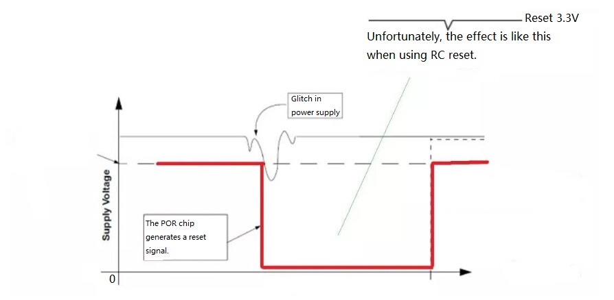
3. Glitch Appears on the Power Supply
This situation in the system work process, if the external interference or the power supply is too bad, VCC will sometimes appear Glitch. If there is a special POR chip to trigger reset, then of course, no problem, but we are using the resistor: the RC reset mode.
Due to the short Glitch time on the power supply, the Reset signal after RC integration has become smaller and smaller, which is not enough to trigger reset (this is the same as the fast hot swap principle above), so it is obvious that the system will crash and when it crashes, it can only be plugged in and unplugged quickly to return to normal.
In order to prove that I have no nonsense, I will extract a paragraph from the Daniel Howard Johnson and ask the reader to read it carefully.
"Power interruptions drive power-on-reset circuits crazy. Consider what a power dropout does to the circuit in Figure 1. Imagine that the RC time constant in this figure is 1 sec. Let VCC come up and stabilize at full voltage for perhaps 10 sec.
Next, apply an ac power interruption just long enough to drop VCC to 0V for about 100 msec. If a processor is involved, the dropout is long enough to make scrambled eggs of the processor's internal state machines but not long enough to discharge the RC circuit. If the RC circuit doesn't discharge, ~RESET doesn't activate, and the processor spins out of control, powered on, but lost in space.”
4. The Power-on Sequence is Destroyed
Someone here can't figure it out. What's the relationship between slower power on and the order of power on? Please see my illustrations as follows:
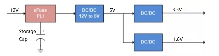
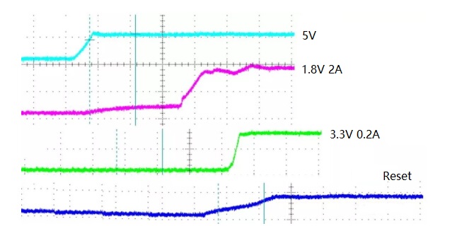
When the following two conditions occur on the 5V, there is a problem (in fact, when the USB 5V is powered, some products have poor power quality, and we cannot predict the 5V output situation).
(1) When 5V is on power, there are steps or trench.
(2) 5V has Dip or Glitch during operation
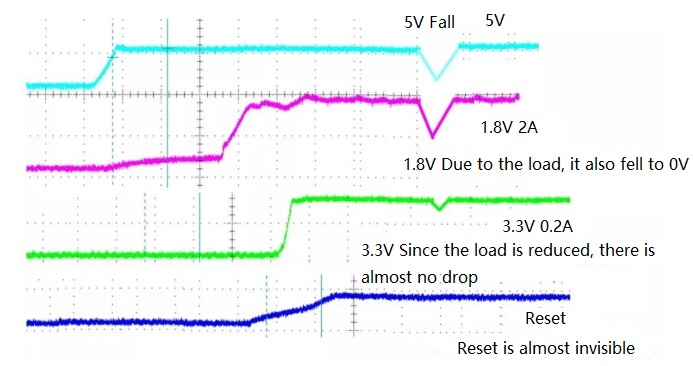
We can see that because of the rapid drop of 5V power supply, 1.8V power will soon be emitted due to heavy load current, falling to 0V, and 3.3V power-on sequence becomes 3.3V = Reset - > 5V - > 1.8V because of light load, too late to discharge, so the drop is very small, so the power-on sequence becomes 3.3V = Reset - > 5V - > 1.8V, which brings two problems:
(1) After re-power on, 3.3V has been in power firstly, since 3.3V is always on. This reverses the requirement of the 1.8V firstly power-on. And the consequence is simple and that is the chip is easy to latch up, and fail to get up, or burn down.
(2) The 3.3V RC reset used this time, because the 3.3V is too late to discharge, the Reset signal does not respond at all. You think about the power of the CPU core has been lost, and the system does not have a reset signal. That's too much to say. Not only the chip can't get up, but also it's very dangerous.
To sum up, when we use the RC method to generate a Reset in a simple MCU system, we need to evaluate the risk. The quality of the power output is very good, and the products that customers often hot swap are not OK. Conversely, if it is a peripheral device that customers often plug and play, it is necessary to carefully select the values of your R and C. On the basis of satisfying the reset time, it is as short as possible, the longer is unsafe. In addition, we should pay attention to testing your power supply circuit to ensure that there are no steps, barbs, and too long rise time.
When hardware engineers sometimes do schematic design, there are many reference designs that can be copied. The problem is that we must know why when we copy other people's schematics, and we can't copy schematic design that have nothing about technical content, only thus we can improve.
You May Also Like:
Prevention and Leveling Method of the Warping in PCB Production
Structures and Applications of the FPCB
Copying the Board, How Should I Copy It?
Ordering & Quality
| Photo | Mfr. Part # | Company | Description | Package | Qty |
|
XC7A200T-2FBG484I | Company:Xilinx | Remark:IC FPGA ARTIX7 285 I/O 484FCBGA | Package:BGA |
XC7A200T-2FBG484I Datasheet |
In Stock:118 Inquiry |
Inquiry |
|
P87C554SBAA,512 | Company:NXP | Remark:IC MCU 8BIT 16KB OTP 68PLCC | Package:68-LCC (J-Lead) |
P87C554SBAA,512 Datasheet |
In Stock:510 Inquiry |
Inquiry |
|
SS15P3S-M3/86A | Company:Vishay | Remark:DIODE SCHOTTKY 30V 15A TO277A | Package:TO-277, 3-PowerDFN |
SS15P3S-M3/86A Datasheet |
In Stock:87640 Inquiry |
Inquiry |
|
D2TO035CR0500FTE3 | Company:Vishay Sfernice | Remark:RES SMD 0.05 OHM 1% 35W TO263 | Package:TO-263-3, D²Pak (2 Leads + Tab), TO-263AB |
D2TO035CR0500FTE3 Datasheet |
In Stock:70 Inquiry |
Inquiry |
|
TMS320DM6433ZWTQ5 | Company:Texas Instruments | Remark:IC DGTL MEDIA PROCESSOR 361-BGA | Package:361-LFBGA |
TMS320DM6433ZWTQ5 Datasheet |
In Stock:485 Inquiry |
Inquiry |
|
RCL1218100RFKEK | Company:Vishay | Remark:RES SMD 100 OHM 1W 1812 WIDE | Package:Wide 1812 (4532 Metric), 1218 |
RCL1218100RFKEK Datasheet |
In Stock:5040 Inquiry |
Inquiry |
|
DS2431+ | Company:Maxim Integrated | Remark:IC EEPROM 1KBIT TO92-3 | Package:TO-226-3, TO-92-3 (TO-226AA) |
DS2431+ Datasheet |
In Stock:857278 Inquiry |
Inquiry |
|
MC908AP64ACFAE | Company:NXP | Remark:IC MCU 8BIT 64KB FLASH 48LQFP | Package:48-LQFP |
MC908AP64ACFAE Datasheet |
In Stock:633 Inquiry |
Inquiry |
|
MAX1490AEPG+ | Company:MAXIM | Remark:IC RS485/RS422 DATA INTRFC 24DIP | Package:PDIP-24 |
MAX1490AEPG+ Datasheet |
In Stock:8428 Inquiry |
Inquiry |
|
MC68332GCEH20 | Company:NXP / Freescale | Remark:IC MCU 32BIT 132PQFP | Package:132-BQFP Bumpered |
MC68332GCEH20 Datasheet |
In Stock:2569 Inquiry |
Inquiry |