14
Introduction
When it comes to Tesla, many people first think of a famous car brand, because this car brand is very famous, it can be said that it is the representative of the top car. But when it comes to Nikola Tesla, many people still know it, because this person can be said to be a physicist wizard in history. His invention can be said to be completely beyond the level of science and technology at the time, so many people say that he is actually an alien, of which the Tesla coil he proposed is a very famous thing. Because according to expectations, this kind of thing can achieve unlimited development of energy, and the principle of Tesla coils is relatively simple, many ordinary people can make Tesla coils. At present, people are still exploring the Tesla coil, after all, the development potential of this kind of thing is very huge.
Catalog
Introduction | |
I Overview of Tesla Coil | 1.1 Inventor of Tesla Coil |
1.2 How the Tesla coil Was Invented | |
1.3 Types of Tesla Coil | |
1.4 The Principle of Tesla Coil | |
1.5 Calculation Formula of Tesla Coil | |
II Applications of Tesla Coil | 2.1 Application of Tesla Coil in Energy receiving |
2.2 Application of Tesla Coil in UAV | |
2.3 Tesla coil and wireless transmission | |
2.4Application of Tesla coil in other aspects | |
III How to Make a Tesla Coil | |
Conclusion | |
I Overview of Tesla Coil
1.1 Inventor of Tesla Coil

The inventor of the Tesla coil was a scientist named Nicholas Tesla, one of the greatest inventors, physicists, mechanical engineers, and electrical engineers in the world. Tesla is considered an important inventor in history, and his contributions to electricity and magnetism were well known in the late 19th and early 20th centuries. His patented and theoretical working forms are based on modern alternating current power (AC) systems, including multi-phase power distribution systems and AC motors, which helped him bring about the second industrial revolution.
1.2 How the Tesla coil Was Invented

The era of inventing the Tesla coil also has to start from the 1990s. Edison, who started with the invention of electric light bulbs, is developing and promoting DC power equipment and DC power systems. And a talented Serbian-American scientist named Nikola Tesla, who created the first small AC motor for mankind in 1883, firmly believed that many obvious advantages of AC power are more suitable for the construction of power systems.
As the scientific research and commercial competition between the two parties intensified, Tesla discovered resonance phenomena across physics, mechanics, acoustics, and electricity in 1890. In the following 1891, the talented scientist used the principle of resonance to create a new type of transformer-the "Tesla Coil", and a great invention was born.
1.3 Types of Tesla Coil
There are actually many types of Tesla coils, because according to different design concepts, Tesla coils can produce different effects, different wiring levels can produce different performances, and the amount of energy can have different functions. Generally speaking, Tesla coils have some of the following types.
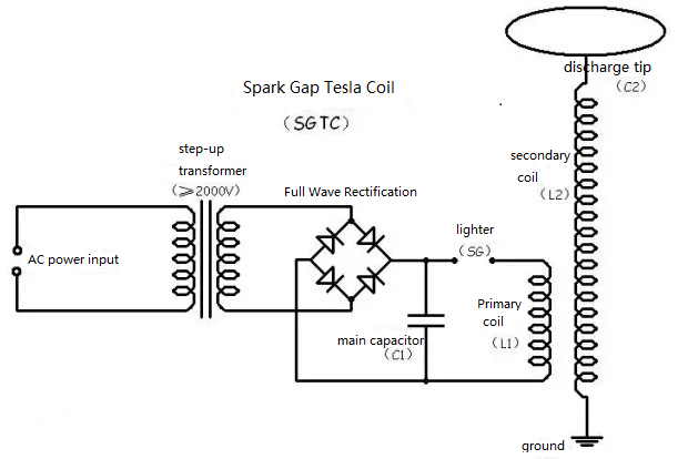
(1) Spark Gap Tesla Coil(SGTC): The "Tesla Coil" invented by Mr. Nicholas Tesla himself belongs to the SGTC. Because the structure and principle are relatively simple, it is also a beginner's entry Tesla coil at this stage.
(2) Solid State Tesla Coil(SSTC): Generally speaking, it is a single-resonant electronic switch Tesla coil. The series resonance does not occur in the primary, and only the secondary can be provided with a frequency that can meet the series resonance in the secondary LC, so that the series resonance occurs in the secondary coil. The primary current is the excitation source voltage divided by the AC impedance.
Advantages: It has the characteristics of low noise, high efficiency and long life, so it has been well developed.
Disadvantages: the primary coil provides limited excitation power to the secondary coil, and the arc is not long.
(3) Off line Tesla Coil(OLTC): When we remove the SGTC lighter, replace it with a MOSFET or IGBT, and use a diode in parallel in parallel with the D and S poles (if IGBT, C and E poles). Then using a solid-state circuit to control this switch and drive it with low voltage to become OLTC. Its basic principle is still LC oscillation, and it is almost the same as SGTC. The difference is that the lighter is replaced by a solid state switch and a low voltage drive is used. Because it is driven by a low voltage and cannot generate too much current, the arc of OLTC is not as spectacular as that of SGTC.
(4) Vacuum tube Tesla coil(VTTC): As the tubes gradually dropped out of our field of vision, a group of tube enthusiasts used them to make a Vacuum tube Tesla coil(VTTC). The tube itself has advantages such as good high-frequency performance, so the VTTC effect is very unique. However, it is undeniable that the tube itself has the disadvantages of high cost, low life, low efficiency, severe heat generation, and easy damage, so VTTC has not been popularized in a wide range.
(5) CW dual-resonant solid-state Tesla: Experiments have shown that the continuous wave (CW) Tesla coils are not long and cluster-like due to the power being played without time constraints.
(6) Double Resonant Tesla Coil(DRSSTC): DRSSTC is essentially a series resonant inverter. Compared with SSTC, the primary coil has series resonance, which causes the voltage across the primary coil inductance to be Q times the voltage of the excitation source. In addition, the resonance impedance Z (R) factor is very low, so the primary resonant current is large(resonant voltage divided by resonance impedance equals resonance current). At this time, the excitation power provided to the secondary will also be large, and SSTC is not an order of magnitude. Compared with SSTC, SSTC's primary coil cannot provide sufficient excitation power to the secondary coil, so the lightning produced by SSTC is less spectacular than a spark gap Tesla coil of the same power level.
DRSSTC's primary coil not only satisfies the conditions for series resonance of the inductance and distributed capacitance of the secondary coil, but also can provide sufficient excitation power to the secondary coil, so the arc length of DRSSTC will be very long. Its advantages are: compared with SGTC, there is no sound and light pollution with spark gap, strong controllability, can play music, high efficiency, long life.
(7) Interrupted SSTC(ISSTC): With the same output power, the arcs of SSTC are clustered and obviously not as spectacular as SGTC. At this time, you can add an arc extinguisher to mimic the work of SGTC, the arc can be longer, and you can use the audio signal to extinguish the signal to play music.
(8) Sidac-IGBT SGTC(SISGTC): A circuit group composed of a trigger diode IGBT tube replaces the traditional spark gap work, and achieves the purpose of eliminating spark noise.
1.4 The Principle of Tesla Coil

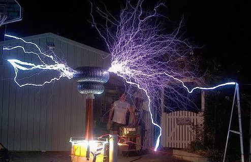
In simple terms, a Tesla coil is a step-up device, scientific name is "distributed parameter high-frequency resonance transformer". It has a two-stage booster coil, which can increase the household 220V voltage to tens of thousands of volts or even hundreds of thousands of volts, and then discharge through the discharge terminal. Due to the high voltage, sparks generated during discharge are like small lightning bolts. On the other hand, the Tesla coil contains an LC oscillating circuit, so the alternating current generated by the discharge terminal has a very high frequency.
Taking household power frequency 50Hz AC as an example, the discharge terminal of a Tesla coil can reach 100kHz to 1.5MHz, which is 2000 to 30,000 times the power frequency. Therefore, Tesla coils can generate ultra-high-voltage but low-current, high-frequency alternating current. First, the power frequency power supply is boosted by a transformer with a boosting ratio of more than 2000, and then the capacitor C1 is charged after passing through the rectifier bridge.
When the voltage of the capacitor exceeds the threshold of the spark gap (SG) to a certain extent, and the spark gap penetrates the air and ignites, the path of the transformer primary coil is formed. The energy oscillates between the capacitor C1 and the primary coil L1 and is transferred to the secondary coil through a coupling. The secondary coil is also an inductor, which can be equivalent to a capacitor between the top cover C2 and the ground, so LC oscillation will also occur. When the two-stage oscillation frequency resonates at the same frequency, the energy of the primary circuit will surge to the secondary, and the peak voltage of the discharge end will continue to increase until the discharge.
1.5 Calculation Formula of Tesla Coil

In the process of making a Tesla coil, whether it is a high-power Tesla coil or a standard-power Tesla coil, engineers need to accurately calculate the values of power, capacitance, voltage, and current according to the corresponding formula. Let's introduce the formula content of those Tesla coils.
(1) Circuit length calculation formula: In the process of making a Tesla coil, the calculation of the circuit length needs to be very accurate, which requires the use of a calculation formula, that is: L=1.7*sqrt(P). In this formula, the arc length is L, the unit is inch, P is the transformer power, the unit is watt, and sqrt is the square.
(2) The calculation formula of the oscillation frequency is F = 1 / [2 * Pi * sqrt (L * C)].
(3) Calculation formula of capacitance array: In the manufacturing process, the formula for calculating the maximum capacity of a Tesla coil capacitor array is also the most commonly used. The formula is C = (10 ^ 6) / [6.2832 * (E / I) * F]. In this formula, E is the transformer output voltage in volts and I is the transformer output current in the range of milliamps. The maximum capacity of the capacitor array is C (in microfarads) and F is the AC frequency (in hertz).
(4) AC peak formula: When the capacitance is too large and the AC rises to the peak, that is, when sqrt (2) * V, the voltage of the capacitor is too low, and the air gap of the lighter cannot be penetrated, the lighter cannot be started, and the entire system will not work.
II Applications of Tesla Coil
2.1 Application of Tesla Coil in Energy receiving

As long as a large Tesla coil is built, even if the number of receiving capacitors continues to increase, it will never affect the output of the power supplied by the coil. In other words, as long as the seat coil outputs 100,000 horsepower of electricity, within 35 miles of the circle, all receiving capacitors can receive 100,000 horsepower, even if an additional 10,000 or 1 million receiving capacitors are added, so that 10,000 One or one million receiving capacitors can also receive 100,000 horsepower in the air.
Because it releases high-voltage and high-frequency currents, it can induce other neutrons in the air to release the same electrons. This is the difference between Tesla coils and general free energy inventions. For example, as long as the city has built Tesla coils in several azimuth locations, every part of the entire city can enjoy life with free electricity.
Unfortunately, this free energy, which has been identified 100 years ago, is still unfairly suppressed. Only a small number of people in various countries are allowed to make it experimentally. It cannot be promoted as one of the main power supply methods.
2.2 Application of Tesla Coil in UAV(Unmanned Aerial Vehicle)
According to the hot trend of the current development of drones, whether it is parcel delivery, farms, or prisoners, this small and flexible aircraft seems to be capable in the future. However, it is not without its shortcomings, the most annoying of which is the problem of insufficient battery life. Most of the drones currently on the market are not allowed to stay in the air for more than 30 minutes on a single charge. After that, you need to replace the battery or connect the power supply to charge.
In fact, the idea of transmitting electrical energy wirelessly was more than a century ago. In 1893, Nicola Tesla, one of the advocates of industrial-grade power applications, showed the "stunt" of "lighting in the next room" at the Columbus Memorial Expo held in Chicago that year. However, compared to Tesla's long-cherished ambitions, this "light bulb" trick does not seem worth mentioning at all. According to his ideas, in the future, using towers and balloons for "broadcasting" can transmit electricity to all parts of the world, and even Tesla successfully applied for JP Morgan Chase's investment for the first trial.
Unfortunately, as predicted by most physicists at the time, Tesla's "wireless power transmission" test ended in failure. Although Tesla's paranoia and love forge have been criticized for some time, it is undeniable that some reliable ways to achieve long-distance power transmission are currently receiving more and more attention.
For example, Tesla's first wireless charging technology has been implemented on mobile phones, and researchers are even developing similar wireless powered kitchen appliances, head-up displays and other military equipment, heart pumps, electroencephalogram and other medical equipment. According to IHS, a well-known research institution in the market, the sales of such equipment are currently around 500 million U.S. dollars in the next 10 years.
2.3 Tesla coil and wireless transmission

When it comes to wireless charging technology, many people think of the famous "Tesla coil". Nikola Tesla, believed to be the creator of the "Tungus Big Bang," invented this high-energy design that could produce artificial lightning. Although it can let electricity spread across the air, it is a little different from what we now call wireless charging. The really similar design is an inductive coil. After one group of coils is energized, the electromagnetic field can be used to generate current in another group of adjacent coils, which has formed the prototype of wireless charging. Although this technology has been around for a hundred years, the difficulty of popularizing wireless charging technology is still very high, and even the biggest beneficiary is actually a charging toothbrush, which is really something that makes people unhappy.
In fact, the real barrier to wireless charging technology lies in the high requirements for short-distance inductive coupling. As a result, for a long time, it could not be really popular, even if the standardized standard Qi has appeared in the industry. However, everything is moving in a good direction. The 4AWP and PMA standards are announced to merge. The Qi standard lineup is also expanding step by step. Microsoft, Panasonic, Samsung, Sony, Toshiba ... even IKEA has said that it will launch new furniture series that supported with Qi standard. The latest Qi standard can achieve a charging distance of 45mm, which is a small breakthrough.
Thanks to wireless charging technology, people can gradually abandon the plug, which just like replaces wired networks with Wi-Fi. And its indicators such as charging speed, stability, and safety will also slowly evolve over time. And besides digital, we can see this kind of technology in more places. At this year's first CES ASIA, we saw a golf concept car from Volkswagen that can drive directly into a specific area and wirelessly charge through the magnetic coil underneath. If future inductive coupling can overcome the limitations of distance and accuracy, it is possible that anything that requires electricity can be recharged at any time. For example, if you are sitting in the living room, and the wireless charging device is located in the study, you can also complete long-distance charging with a single click of the mobile app. In this way, you don't need to worry about finding that the battery of the mobile phone has reached the bottom when you walk into the toilet-as long as it hasn't shut down automatically. Now Starbucks has also introduced Qi wireless charging technology in some stores. If the distance is broken, there will be a group of dynamos in addition to those on the door.
If the expected wireless charging effect in the future is compared to Wi-Fi technology, today's wireless charging mode is not even Bluetooth level. But we believe that small progress over time will accumulate great success, and all this will happen in the near future.
2.4 Application of Tesla coil in other aspects
Tesla coils consist of two (sometimes three) coupled resonant circuits. Because Tesla coils are difficult to define, Nikola Tesla tried a large number of various coil configurations. Tesla uses these coils for innovative experiments such as electrical lighting, fluorescence spectroscopy, X-rays, high-frequency AC current phenomena, electrotherapy, and wireless power for power transmission.
III How to Make a Tesla Coil
This Video Mainly Explains The Steps On How To Make A Tesla Coil At Home
In fact, when it comes to the role of Tesla coils, many folk technology lovers currently like Tesla coils very much. Because this kind of thing can be manufactured by itself, that is to say, as long as you have technical knowledge, then it is very possible to make Tesla coils by yourself. And because the Tesla coil is very beautiful, it has become a favorite thing for viewers. Let's teach everyone how to make a Tesla coil.
a. Fabrication of primary coil: It is wound into a cylindrical shape with 2mm enameled wire, similar to a flattened spring, with a diameter of 7.5 cm and seven turns. At this step, it is recommended to find a small piece of plastic tube with a diameter of 7.5 cm to wind it. This is easy to wind, it is relatively strong, and there is no space between the lines as much as possible.
b. Fabrication of secondary coil: Using 0.25mm enameled wire to wind the pipe. The wires cannot cross, and they must be wound 1000 times. Try to ensure that there is no gap between the wires. If possible, you can use a layer of insulating paint. For secondary coils, we must follow two principles: first, the wires cannot cross; second, the windings must be tight. Because the surface of the enameled wire is covered with a layer of lacquer, you must first drill a small hole in the section of the pipe, then fix the end of the wire with glue, and then start winding.
c. Assemble the coil: Connecting one end of the wire of the secondary coil to that metal ball. This ball is called the tip of the discharge. It forms a capacitor with the ground, and then fixes the ball to the end of the tube with a glue or hot glue gun. The secondary coil is fixed on a plastic plate, the primary coil is fixed near the secondary coil, and the other end of the wire of the secondary coil is grounded. In this way, we first fixed the primary coil with glue in the middle of the plexiglass plate (assuming that the plexiglass plate was purchased), and then fixed the secondary coil in the middle of the primary coil. Then, remove a small piece of varnish from one end of the enameled wire on the secondary coil, attach it to the ball, and fix the ball.
d. Combined capacitor: We need some non-polarity capacitors. It is recommended to use MKPH capacitors or ceramic capacitors. According to the data of this coil, the result of the calculation is that a 0.022μF capacitor is needed (can be fine-tuned according to the lighter spacing). The withstand voltage of the capacitor depends on the voltage of the power supply, and the high voltage package can generate a voltage of 10,000 to 20,000 volts, so the better is the higher withstand voltage of the capacitor. The withstand voltage of the series capacitor is equal to the sum of the withstand voltage of each capacitor, and the inverse of the capacity is equal to the sum of the inverse of the capacity of each capacitor. The withstand voltage of the parallel capacitor is unchanged, and the capacity is equal to the sum of the capacities of the capacitors.
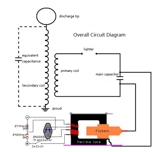
e. Power production: High pressure can be generated by single tube self-excitation. First we use a 2N3055 transistor, and the black thing in the picture is the core of the high voltage package. The two coils wound on the ferrite are wound eight times and twenty times with 1mm enameled wire from top to bottom, especially the directions of the windings must be the same. At the same time, it is better to install a heat sink for the triode, because the self-excitation of a single tube will generate high temperature, and it will not burn the triode if the temperature is not too high.
f. Making a lighter: The principle of SGTC is to charge the capacitor first. When the voltage of the capacitor reaches a certain level, an arc is emitted from the lighter to form a circuit, and then the circuit is discharged, and then the cycle is restarted. We can make lighters with a slightly thicker enameled wire. Generally, lighters cannot be sharpened and need a smooth surface. Therefore, the skin on one end of the two pieces of rough enameled wire should be scraped off, bent into two smooth surfaces, and then fixed on the plastic board with a hot glue gun, leaving a gap of 6-10 mm in the middle.
g. Final assembly: As shown below:

Conclusion
When it comes to Tesla, there is also a famous Tunguska explosion associated with it. Many people have speculated that it is related to Tesla's experiment. This explosion can be said to be unprecedented, and its explosive equivalent is very horrible. Obviously, the level of explosives at that time could not be reached, and at this time, it was exactly the test stage of Tesla. Although it was not directly stated, many people still said that it was caused by Tesla. Compared with this kind of nothingness, we should pay more attention to what wonderful Tesla coils can bring us in the future.
You May Also Like:
Wireless Charging Technology | How dose Wireless Charge Works, Application and Standards
Features, Development Trends and Disadvantages of Wireless Power Transfer
Ordering & Quality
| Photo | Mfr. Part # | Company | Description | Package | Qty |
|
A3P030-1QNG48I | Company:Microsemi | Remark:IC FPGA 34 I/O 48QFN | Package:48-VFQFN Exposed Pad |
A3P030-1QNG48I Datasheet |
In Stock:146 Inquiry |
Inquiry |
|
K4S561632N-LC60 | Company:SAMSUNG | Remark:consumer memory | Package:TSOP |
K4S561632N-LC60 Datasheet |
In Stock:15960 Inquiry |
Inquiry |
|
MR27T12800J | Company:OKI | Remark: | Package:TSSOP-48 |
MR27T12800J Datasheet |
In Stock:710 Inquiry |
Inquiry |
|
CY62157DV30LL-55ZSXI | Company:Cypress Semiconductor Corp | Remark:IC SRAM 8MBIT 55NS 44TSOP | Package:44-TSOP (0.400", 10.16mm Width) |
CY62157DV30LL-55ZSXI Datasheet |
In Stock:1200 Inquiry |
Inquiry |
|
ADSP-BF533SBBCZ500 | Company:Analog Devices | Remark:IC DSP CTLR 16B 500MHZ 160CSPBGA | Package:BGA |
ADSP-BF533SBBCZ500 Datasheet |
In Stock:1258 Inquiry |
Inquiry |
|
MPC8544CVTALFA | Company:NXP / Freescale | Remark:IC MPU MPC85XX 667MHZ 783FCBGA | Package:BGA |
MPC8544CVTALFA Datasheet |
In Stock:69 Inquiry |
Inquiry |
|
70V34L20PFI8 | Company:IDT | Remark:SRAM 4K x 18 3.3V Dual-Port RAM | Package: |
70V34L20PFI8 Datasheet |
In Stock:95 Inquiry |
Inquiry |
|
MC56F82743VLC | Company:NXP / Freescale | Remark:IC MCU 32BIT 64KB FLASH 32LQFP | Package:N/A |
MC56F82743VLC Datasheet |
In Stock:83 Inquiry |
Inquiry |
|
MPC8360ECZUAJDGA | Company:Freescale Semiconductor - NXP | Remark:IC MPU MPC83XX 533MHZ 740TBGA | Package:740-LBGA |
MPC8360ECZUAJDGA Datasheet |
In Stock:73 Inquiry |
Inquiry |
|
MC711K4CFNE3 | Company:NXP / Freescale | Remark:IC MCU 8BIT 24KB OTP 84PLCC | Package:84-LCC (J-Lead) |
MC711K4CFNE3 Datasheet |
In Stock:7832 Inquiry |
Inquiry |