13
In the fields of medical equipment, automotive instrumentation, and industrial control, when equipment design involves strain gauges, sensor interfaces, and current monitoring, precision analog front-end amplifiers are often required to extract and amplify very weak real signals and suppress common unwanted signals such as mode voltage and noise.
First, the designer will concentrate on ensuring that the device and the accuracy parameters such as noise, offset, gain, and temperature stability meet the application requirements. The designer then selects the front-end analog device that meets the total error budget based on the above characteristics. However, there is a frequently overlooked problem in such applications, namely high frequency interference caused by external signals, also known as "electromagnetic interference (EMI)." EMI can occur in a variety of ways, primarily by the final application. For example, an instrumentation amplifier may be used in a control board that interfaces with a DC motor, and the current loop of the motor contains power leads, brushes, commutators, and coils, which typically emit high-frequency signals like an antenna, and may A small voltage that interferes with the input of the instrumentation amplifier.
Another example is current sensing in automotive solenoid valve control. Solenoid valves are powered by the vehicle's battery through long wires that act like antennas. A series shunt resistor is connected to the wire path, and then the voltage across the resistor is measured by a current sense amplifier. A high frequency common mode signal may be present in the line, and the input of the amplifier is susceptible to such external signals. Once affected by external high-frequency interference, the accuracy of the analog device may be degraded and the solenoid valve circuit may not be controlled. This state of performance in the amplifier is that the amplifier output accuracy exceeds the error budget and the tolerances in the data sheet, and in some cases may reach the limit, causing the control loop to turn off.
How Solenoid Valves Work?
How does EMI cause large DC deviation? It may be that many instrumentation amplifiers are designed to exhibit excellent common-mode rejection in the frequency range up to tens of kilohertz depending on the design. However, when an unshielded amplifier is exposed to tens or hundreds of "megahertz" RF radiation, problems can occur. At this point, the input stage of the amplifier may be asymmetrical rectified, resulting in a DC deviation. After further amplification, it will be very noticeable, plus the gain of the amplifier, even reaching the upper limit of its output or part of the external circuit.
Example of How High Frequency Signals Affect Analog Devices
This example will introduce in detail a typical high end current detection application.
Figure 1 shows common configurations for monitoring solenoid valves or other inductive loads in automotive application environments.
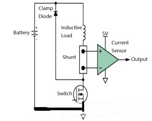
Figure 1. High-end Current Monitoring
We use two current detection amplifiers with similar designs to study the effect of high frequency interference. The function and pin alignment of these two devices are identical; however, one has built-in EMI filter circuit, while the other has not.
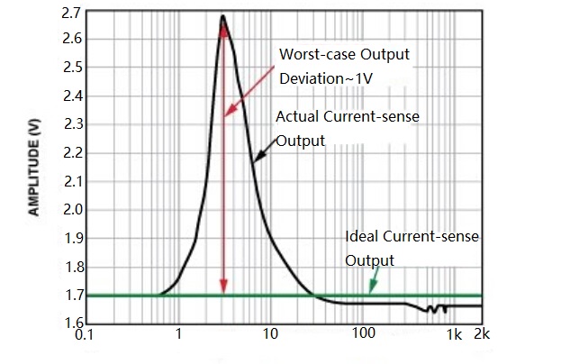
Figure 2. Current Sensor Output (No built-in EMI filter, forward power = 12 dBm, 100 mV/divide, DC output peaks at 3 MHz)
Figure 2 shows the deviation of the DC output of the current sensor from its ideal value as the input changes over a wide frequency range. It can be seen from the figure that the deviation is most significant (>0.1 V) in the frequency range from 1 MHz to 20 MHz, and the DC error reaches a maximum value (1 V) at 3 MHz, which is 0 V to 5 V in the amplifier. A large proportion of the output voltage range is occupied.
Figure 3 shows the results of the same experiment and configuration when using another pin-compatible current sensor with the same circuit architecture and similar DC specifications as the previous example, but with an input EMI filter circuit. Note that the voltage range has been expanded by a factor of 20.
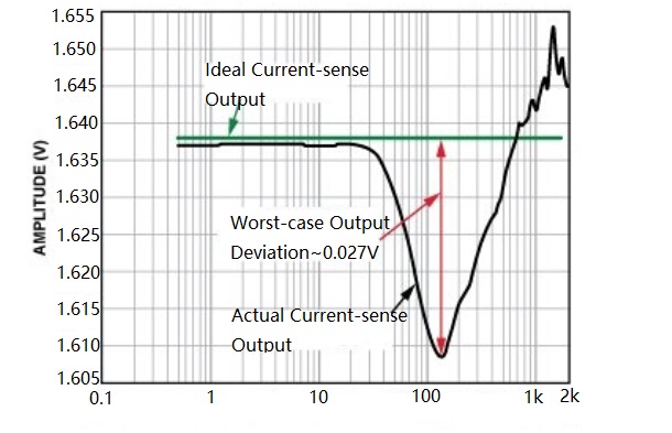
Figure 3. Current Sensor Output (built-in EMI filter, forward power = 12 dBm, 5 mV/frequency division, peak DC output at > 100 MHz)
In this case, the error at 40 MHz is only about 3 mV, and the peak error (greater than 100 MHz) is less than 30 mV, which improves the performance by 35 times. This clearly shows that the built-in EMI filter circuit can significantly improve the protection performance of the current sensor and protect it from the high frequency signal at the input end. In practical applications, although the severity of EMI is not clear, if the current sensor with built-in EMI filtering function is used, the control loop will actually remain within its tolerance range.
Both devices were tested under exactly the same conditions. The only difference is that the AD8208 is equipped with an internal low-pass RF input filter on both the input and power pins. Adding such components to the chip seems trivial, but since the application is typically controlled by PWM, the current sense amplifier must be able to withstand a continuous switching common-mode voltage of up to 45 V. Therefore, to maintain accurate high gain and common mode rejection, the input filters must be closely matched.
You May Also Like:
Features, Developemnt Trends and Disadvantages of Wireless Power Transfer
Eliminate Electromagnetic Interference Solutions for Single-chip Systems
How to Judge Whether IC is Working Correctly in Electronic Circuit or Not
24 Classic Circuits Consisting of Bidirectional General Purpose Operational Amplifier LM358
Ordering & Quality
| Photo | Mfr. Part # | Company | Description | Package | Qty |
|
TMS320DM6433ZWTQ5 | Company:Texas Instruments | Remark:IC DGTL MEDIA PROCESSOR 361-BGA | Package:361-LFBGA |
TMS320DM6433ZWTQ5 Datasheet |
In Stock:485 Inquiry |
Inquiry |
|
BCM7501KFB P20 | Company:BROADCOM | Remark:IC Chips | Package:BGA64 |
BCM7501KFB P20 Datasheet |
In Stock:19250 Inquiry |
Inquiry |

|
MC9S08QD4CSC | Company:NXP | Remark:IC MCU 8BIT 4KB FLASH 8SOIC | Package:SOIC8 |
MC9S08QD4CSC Datasheet |
In Stock:41393 Inquiry |
Inquiry |
|
MC68360ZQ25L | Company:Freescale Semiconductor - NXP | Remark:IC MPU M683XX 25MHZ 357BGA | Package:BGA |
MC68360ZQ25L Datasheet |
In Stock:811 Inquiry |
Inquiry |
|
RL7520WS-R10-F | Company:Susumu | Remark:RES SMD 0.1 OHM 2W 3008 WIDE | Package:Wide 3008 (2075 Metric), 0830 |
RL7520WS-R10-F Datasheet |
In Stock:19360 Inquiry |
Inquiry |
|
STM32F103C8T6 | Company:STMicroelectronics | Remark:IC MCU 32BIT 64KB FLASH 48LQFP | Package:LQFP-48 |
STM32F103C8T6 Datasheet |
In Stock:45000 Inquiry |
Inquiry |
|
S912XEQ512J3MAA | Company:NXP / Freescale | Remark:IC MCU 16BIT 512KB FLASH 80QFP | Package:80-QFP |
S912XEQ512J3MAA Datasheet |
In Stock:98 Inquiry |
Inquiry |
|
MCIMX353DJQ5C | Company:NXP / Freescale | Remark:IC MPU I.MX35 532MHZ 400MAPBGA | Package:400-LFBGA |
MCIMX353DJQ5C Datasheet |
In Stock:24833 Inquiry |
Inquiry |
|
MC9S08PT32VLC | Company:NXP | Remark:IC MCU 8BIT 32KB FLASH 32LQFP | Package:32-LQFP |
MC9S08PT32VLC Datasheet |
In Stock:103 Inquiry |
Inquiry |
|
RC0603FR-071KL | Company:Yageo | Remark:RES SMD 1K OHM 1% 1/10W 0603 | Package:SMD |
RC0603FR-071KL Datasheet |
In Stock:39061200 Inquiry |
Inquiry |