6
The author perfected this article on December 27, 2019
Abstract
The ratio of the output signal to the input signal, the relationship between the signal current or voltage and the circuit parameters, the relationship between the amplitude and frequency, phase and frequency of the signal in the circuit, the parameters to be considered for component selection and so on, all of these are required to master.
Catalog
I Three levels of Mastering Analog Circuit | 1. Primary level |
2. Intermediate level | |
3. Advanced level | |
II Simple Analog Circuit Examples | 1. Bridge Rectifier |
2. Power Filter | |
3. Signal Filter | |
4. Differentiating Circuit and Integrating Circuit | |
5. Common Emitter (CE) Amplifier Circuit | |
6. Voltage-Divider Biased Common-Emitter Amplifier | |
7. Common Collector Amplifier (Emitter Follower) | |
8. Circuit Feedback Block Diagram | |
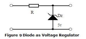
9. Diode as Voltage Regulator | |
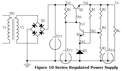
10. Series Regulated Power Supply | |
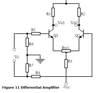
11. Differential Amplifier | |
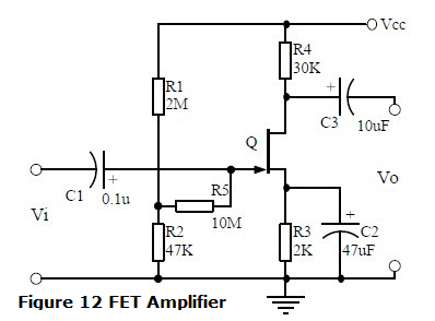
12. FET Amplifier | |
13. Frequency Selective (Bandpass) Amplifier | |
14. Differential Amplifier | |
15. Voltage Comparator | |
16. RC Oscillator | |
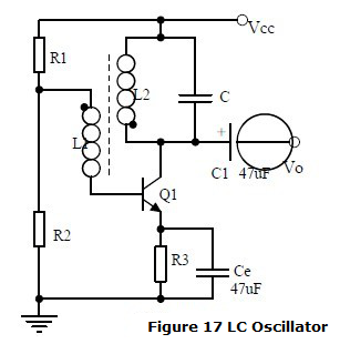
17. LC Oscillator | |
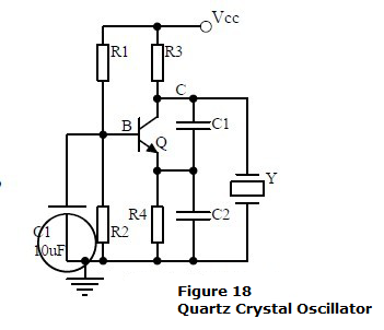
18. Quartz Crystal Oscillator | |
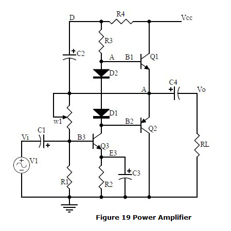
19. Power Amplifier | |
III Book Recommendations | |
I Three levels of Mastering Analog Circuit
The mastery of analog circuits is divided into three levels:
1.Primary level: skillfully memorize the twenty circuits and understand their roles. Both electronics lovers and electrical and electronics engineering majors, should and could remember these twenty basic analog circuits.
2. Intermediate level: can analyze the role of key components in these twenty circuits, what are the effects on the function of the circuit when each component fails, how the parameters change during measurement, and how to handle faulty components. Qualitatively analyze the direction of signal flow and phase change, how the signal waveform changes, and qualitatively understand the input and output impedance and how they affect the signal. With these knowledge of circuits, you are very likely to grow into an outstanding maintenance technician for electronic products and industrial control equipment.
3. Advanced level: the input and output impedance of the twenty circuits can be calculated quantitatively. In addition, the ratio of the output signal to the input signal, the relationship between the signal current or voltage and the circuit parameters, the relationship between the amplitude and frequency, phase and frequency of the signal in the circuit, the parameters to be considered for component selection and so on, all of these are required to master. At the advanced proficiency level, if you like, a design and development engineer, the well-respected high-paying occupation, for electronic products and industrial control equipment, will be your first choice.
Bob Dobkin on Analog Circuit Design
II Simple Analog Circuit Examples
1. Bridge Rectifier
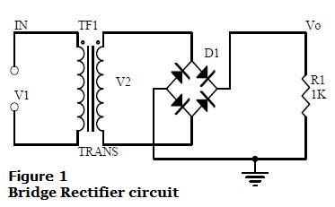
Please consider the following questions:
(1) Unidirectional conductivity of diodes;
(2) I–V curve;
(3) Ideal switch model and constant voltage drop (CVD) model;
(4) How electric current flow in a bridge rectifier circuit;
(5) Input and output waveforms;
(6) Figure out: Vo, Io and reverse voltage of the diode.
2. Power Filter
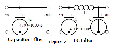
Please consider the following questions:
(1) Process analysis of Power filter;
(2) How is the wave formed;
(3) Figure out: size and permissible voltage of the filter capacitor.
3. Signal Filter
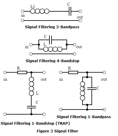
Please consider the following questions:
(1) The role of signal filters;
(2) Differences and similarities between signal filter and power filter;
(3) Impedance calculations for series and parallel R LC circuits;
(4) Amplitude-frequency & phase-frequency curves;
(5) Determining the passband curve;
(6) Calculating the resonant frequency.
4. Differentiating Circuit and Integrating Circuit
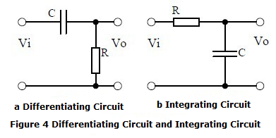
Please consider the following questions:
(1) The role of the circuits, the differences and similarities with the filter.
(2) The voltage variation process of differentiating and integrating Circuits is analyzed and the waveform of voltage variation is drawn.
(3) Draw the waveforms of voltage variation.
(4) Figure out: time constant, voltage variation equation, resistance and capacitance parameters.
5. Common Emitter (CE) Amplifier Circuit
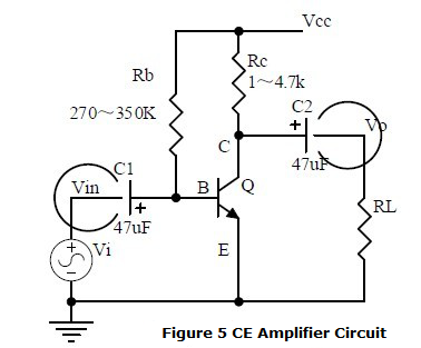
Please consider the following questions:
(1) BJT structure, current relationship of each terminal of BJT, characteristic curve and amplification conditions.
(2) The role of the components, the use of the circuit, the amplification of voltage, the phase relationships between the input and output voltages and the AC
(3) and DC equivalent circuits.
(4) Figure out the operating point and the amplification of voltage.
A video showing how to do AC analysis of a common emitter amplifier.
AC analysis involves figuring out the voltage gain, the input impedance and the output impedance of the amplifier.
6. Voltage-Divider Biased Common-Emitter Amplifier
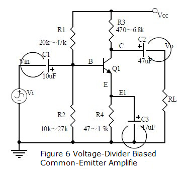
Please consider the following questions:
(1) The role of the components, the use of the circuit, the amplification of voltage, the phase relationships between the input and output voltages and the AC and DC equivalent circuits.
(2) Analysis of series circuits with current negative feedback and effect of the negative feedback on the circuit parameters.
(3) Figure out the operating point and the amplification of voltage.
7. Common Collector Amplifier (Emitter Follower)
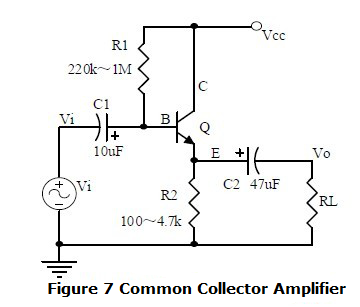
Please consider the following questions:
(1) The role of the components, the use of the circuit, the amplification of voltage, the phase relationships between the input and output voltages, the AC and DC equivalent circuits and characteristics of the input and output impedance of the circuit.
(2) Analysis of series circuits with current negative feedback and effect of the negative feedback on the circuit parameters.
(3) Figure out the operating point and the amplification of voltage.
8. Circuit Feedback Block Diagram
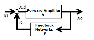
Please consider the following questions:
(1) The concept of feedback, positive feedback vs. negative feedback, shunt feedback vs. series feedback.
(2) Amplification gain of negative feedback circuit.
9. Diode as Voltage Regulator
For each of the rest following circuit, the analyses (the points you should pay attention to) would go on as a same way.
10. Series Regulated Power Supply
11. Differential Amplifier
12. FET Amplifier
13. Frequency Selective (Bandpass) Amplifier
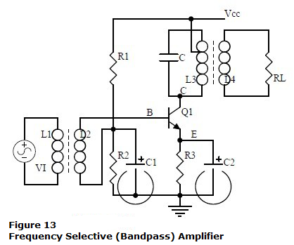
14. Differential Amplifier
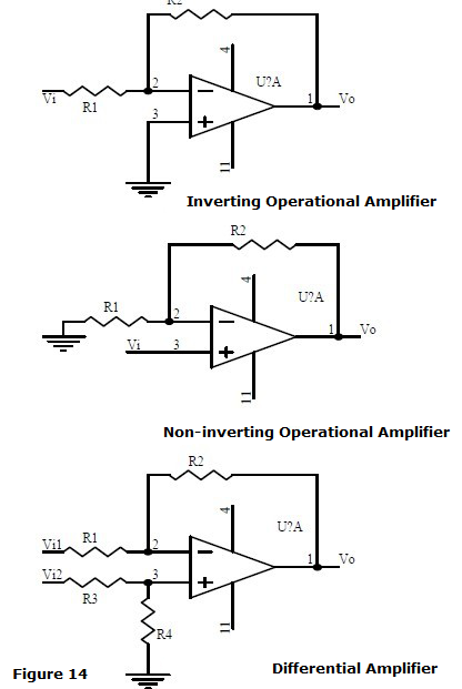
15. Voltage Comparator
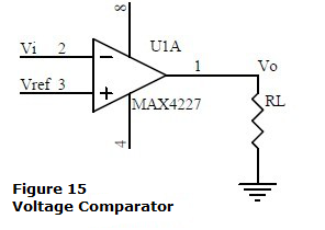
16. RC Oscillator
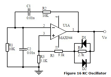
17. LC Oscillator
18. Quartz Crystal Oscillator
19. Power Amplifier
III Book Recommendations
1. Analog Circuit Design : Art, Science, and Personalities (The EDN Series for Design Engineers) 1991
Combines theory and applications with the philosophies behind the design process of analog circuit design. Readers are shown how designers approach problems and how they think about solutions to those problems, and are taught the "analog way" - a broad method of thinking about analog design tasks.
by Jim (ed.) Williams
2. Electrical Engineering 101, Third Edition: Everything You Should Have Learned in School...but Probably Didn't
Unlike other books that simply describe electronics and provide step-by-step build instructions, EE101 delves into how and why electricity and electronics work, giving the reader the tools to take their electronics education to the next level. It is written in a down-to-earth style and explains jargon, technical terms and schematics as they arise. The author builds a genuine understanding of the fundamentals and shows how they can be applied to a range of engineering problems.
by Darren Ashby
Hope this article could help you a little bit, and you're always welcomed to visit our website again for more technological articles and news.
Ordering & Quality
| Photo | Mfr. Part # | Company | Description | Package | Qty |
|
ADSP-21065LKSZ-264 | Company:Analog Devices | Remark:IC DSP CONTROLL 544KBIT 208-MQFP | Package:QFP |
ADSP-21065LKSZ-264 Datasheet |
In Stock:992 Inquiry |
Inquiry |
|
MC68360ZQ25L | Company:Freescale Semiconductor - NXP | Remark:IC MPU M683XX 25MHZ 357BGA | Package:BGA |
MC68360ZQ25L Datasheet |
In Stock:811 Inquiry |
Inquiry |
|
W631GG6KB-15 | Company:Winbond Electronics | Remark:IC DRAM 1G PARALLEL 96WBGA | Package:FBGA |
W631GG6KB-15 Datasheet |
In Stock:3070 Inquiry |
Inquiry |
|
K4S561632N-LC60 | Company:SAMSUNG | Remark:consumer memory | Package:TSOP |
K4S561632N-LC60 Datasheet |
In Stock:15960 Inquiry |
Inquiry |
|
A3P030-1QNG48I | Company:Microsemi | Remark:IC FPGA 34 I/O 48QFN | Package:48-VFQFN Exposed Pad |
A3P030-1QNG48I Datasheet |
In Stock:146 Inquiry |
Inquiry |
|
P87C554SBAA,512 | Company:NXP | Remark:IC MCU 8BIT 16KB OTP 68PLCC | Package:68-LCC (J-Lead) |
P87C554SBAA,512 Datasheet |
In Stock:510 Inquiry |
Inquiry |
|
DS1816R-5+T&R | Company:Maxim Integrated | Remark:IC 3.06V OD 5% SOT23-3 | Package:TO-236-3, SC-59, SOT-23-3 |
DS1816R-5+T&R Datasheet |
In Stock:7060 Inquiry |
Inquiry |
|
MC14600P | Company:Freescale Semiconductor - NXP | Remark:IC ALARM GENERAL MONO 16-DIP | Package:16-DIP (0.300", 7.62mm) |
MC14600P Datasheet |
In Stock:1177 Inquiry |
Inquiry |
|
MC9RS08KB2CSC | Company:NXP | Remark:IC MCU 8BIT 2KB FLASH 8SOIC | Package:8-SOIC (0.154", 3.90mm Width) |
MC9RS08KB2CSC Datasheet |
In Stock:10913 Inquiry |
Inquiry |
|
W29W640GT70ZF6 | Company:ST | Remark: | Package:BGA |
W29W640GT70ZF6 Datasheet |
In Stock:2200 Inquiry |
Inquiry |