| Manufacturer Part#: | MR82C54 |
| Product Category: | IC chips |
| Manufacturer: | NTERSIL |
| Description: | |
| Package: | CLCC |
| Quantity: | 455 PCS |
| Lead Free Status / RoHS Status: | Lead free / RoHS Compliant |
| one to seven days | |
| Click buy button to purchase: | Buy |
DESCRIPTION
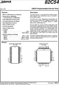
The Intersil is a high performance CMOS Programmable Interval Timer manufactured using an advanced 2 micron CMOS process. The 82C54 has three independently programmable and functional 16-bit counters, each capable of handling clock input frequencies 12MHz (82C54-12). The high speed and industry standard configuration of the 82C54 make it compatible with the Intersil 80C86, 80C88, and 80C286 CMOS microprocessors along with many other industry standard processors. Six programmable timer modes allow the to be used as an event counter, elapsed time indicator, programmable one-shot, and many other applications. Static CMOS circuit design insures low power operation. The Intersil advanced CMOS process results in a significant reduction in power with performance equal to or greater than existing equivalent products.
APPLICATION
to 12MHz Clock Input Frequency Compatible with NMOS 8254 - Enhanced Version of NMOS 8253 Three Independent 16-Bit Counters Six Programmable Counter Modes Status Read Back Command Binary or BCD Counting Fully TTL Compatible Single 5V Power Supply Low Power ICCSB.10μA - ICCOP. at 8MHz Operating Temperature Ranges to +125oC
CAUTION: These devices are sensitive to electrostatic discharge; follow proper IC Handling Procedures. http://www.intersil.com 407-727-9207 | Copyright c Intersil Corporation 1999
PART NUMBERS MD82C54/B MR82C54/B SMD # 8406501JA SMD# 84065023A CM82C54-12 TEMPERATURE RANGE to +70oC PACKAGE 24 Lead PDIP 24 Lead PDIP 28 Lead PLCC 28 Lead PLCC 24 Lead CERDIP 24 Lead CERDIP 24 Lead CERDIP 28 Lead CLCC 24 Lead CERDIP 28 Lead CLCC 24 Lead SOIC PKG. NO. J28.A M24.3
DATA/ BUS BUFFER CLK 0 COUNTER 0 GATE 0 OUT 0 CONTROL WORD REGISTER A1 CS CLK 2 CONTROL WORD REGISTER COUNTER 2 GATE 2 OUT 2 GATE n CLK n OUT n COUNTER INTERNAL BLOCK DIAGRAM READ/ WRITE LOGIC INTERNAL BUS COUNTER 1 CLK 1 GATE 1 OUT 1 CONTROL LOGIC CE STATUS LATCH CRM STATUS REGISTER CRL INTERNAL BUS
SYMBOL - D0 CLK 0 OUT 0 GATE 0 GND OUT 1 GATE 1 CLK 1 GATE 2 OUT 2 DIP PIN NUMBER TYPE I/O O I DEFINITION DATA: Bi-directional three-state data bus lines, connected to system data bus. CLOCK 0: Clock input of Counter 0. OUT 0: Output of Counter 0. GATE 0: Gate input of Counter 0. GROUND: Power supply connection. OUT 1: Output of Counter 1. GATE 1: Gate input of Counter 1. CLOCK 1: Clock input of Counter 1. GATE 2: Gate input of Counter 2. OUT 2: Output of Counter 2.
SYMBOL CLK A0, A1 DIP PIN NUMBER (Continued) TYPE I CLOCK 2: Clock input of Counter 2. ADDRESS: Select inputs for one of the three counters or Control Word Register for read/write operations. Normally connected to the system address bus. RD WR VCC I A0 SELECTS Counter 0 Counter 1 Counter 2 Control Word Register DEFINITION
CHIP SELECT: A low on this input enables the 82C54 to respond to RD and WR signals. RD and WR are ignored otherwise. READ: This input is low during CPU read operations. WRITE: This input is low during CPU write operations. VCC: The +5V power supply pin. A 0.1μF capacitor between pins VCC and GND is recommended for decoupling.
General The is a programmable interval timer/counter designed for use with microcomputer systems. is a general purpose, multi-timing element that can be treated as an array of I/O ports in the system software. The 82C54 solves one of the most common problems in any microcomputer system, the generation of accurate time delays under software control. Instead of setting up timing loops in software, the programmer configures the 82C54 to match his requirements and programs one of the counters for the desired delay. After the desired delay, the 82C54 will interrupt the CPU. Software overhead is minimal and variable length delays can easily be accommodated. Some of the other computer/timer functions common to microcomputers which can be implemented with the 82C54 are: Real time clock Event counter Digital one-shot Programmable rate generator Square wave generator Binary rate multiplier Complex waveform generator Complex motor controller Data Bus Buffer This three-state, bi-directional, 8-bit buffer is used to interface the 82C54 to the system bus (see Figure 1).
FIGURE 1. DATA BUS BUFFER AND READ/WRITE LOGIC FUNCTIONS
CONTROL WORD REGISTER COUNTER - D0 DATA/ BUS BUFFER CLK 0 COUNTER 0 GATE 0 OUT 0
Read/Write Logic The Read/Write Logic accepts inputs from the system bus and generates control signals for the other functional blocks of the 82C54. A1 and A0 select one of the three counters or the Control Word Register to be read from/written into. A "low" on the RD input tells the 82C54 that the CPU is reading one of the counters. A "low" on the WR input tells the 82C54 that the CPU is writing either a Control Word or an initial count. Both RD and WR are qualified by CS; RD and WR are ignored unless the 82C54 has been selected by holding CS low.
FEATURES
• 8MHz to 12MHz Clock Input Frequency
• Compatible with NMOS 8254
- Enhanced Version of NMOS 8253
• Three Independent 16-Bit Counters
• Six Programmable Counter Modes
• Status Read Back Command
• Binary or BCD Counting
• Fully TTL Compatible
• Single 5V Power Supply
• Low Power
- ICCSB . . . . . . . . . . . . . . . . . . . . . . . . . . . . . . . . . .10µA
- ICCOP . . . . . . . . . . . . . . . . . . . . . . . . . . 10mA at 8MHz
• Operating Temperature Ranges
- C82C54 . . . . . . . . . . . . . . . . . . . . . . . . . .0oC to +70oC
- I82C54 . . . . . . . . . . . . . . . . . . . . . . . . . -40oC to +85oC
- M82C54 . . . . . . . . . . . . . . . . . . . . . . . -55oC to +125oC
SPECIFICATION
| Manufacturer | INTERSIL |
| Product Category | IC Chips |
RELEVANT POPULAR RESEARCHES
| 3.6 V 2.3 V UART Interface IC | PLCC-44 UART Interface IC |
| 4 Channel UART Interface IC | 1 Channel UART Interface IC |
| SMD/SMT 4 Channel UART Interface IC | TSSOP-28 UART Interface IC |
PICTURE
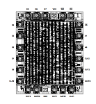
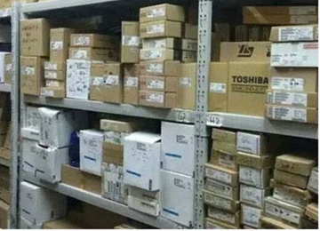

MR82C54 image
 IC RS485/RS422 DATA INTRFC 24DIP
 low cost precision device designed for general purpose application
 CAP CER 0.022UF 50V X7R RADIAL