5
The author perfected the content of this article on December 31th
Introduction
The circuit of high frequency transformer is shown in figure 1.
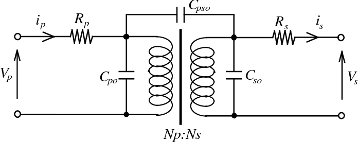
FIG.1 Circuit of high frequency transformer
This Video Shows One of The Many Ways That Exist To Home Made or Build a Electric Transformer That Meets the Technical Requirements Necessary For Use in Our Electronic Projects.
Catalog
Introduction | |
I Detail & Analyses | 1.1 Confirmation Materials |
1.2 Methods for Winding Coils | |
II Wrapping Copper Foils | 2.1 Copper Foil Winding Method |
2.2 Requirements For Using Copper Foil in Transformers | |
III Pressing Coil | |
IV Soldering Tin | 4.1 Procedures for Soldering |
4.2 Requirements | |
4.3 Matters Needing Attention | |
V Core Assembly | 5.1 Processes |
5.2 Matters Needing Attention in Assembling Iron Core | |
VI Impregnation | 6.1 Operating Procedures |
6.2 Matters Needing Attention | |
VII Labeling (or printing) | |
VIII Exterior | |
IX Electrical Test | |
X Book Suggestions | |
I Detail & Analyses
1.1 Confirmation Materials
1) Confirm the specifications of Transformer Bobbins.
2) When the unneeded pin is about to be cut, it should be cut before being wound, in case it will scrape the wire or you yourself will cut or wind the wrong pin.
3) Make sure the Bobbin is complete and there must be no damage or cracks.
4) Insert the Bobbin correctly into the jig, generally marked as pin 1 which towards the machine if the surface is not indicated.
5) Wrap the bobbins needed with insulating acetate cloth adhesive tape according to the requirements of schedule drawing, which is wrapped close to the sides of the Bobbin; start to hook and wind wires on the specified pins within the winding space.
1.2 Methods for Winding Coils
According to different transformer requirements, the winding method can be roughly divided into the following types:
① Thick single-layer winding: the wiring only occupies one layer and there is no gap between the neat wires.
② Equidistant winding: the winding is performed at equal intervals within the winding space; winding interval error can be accepted within 20%.
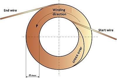
FIG.2 Winding Coils
③ Thick multi-layer winding: when one layer is not enough for the requirements, the windings now must be wound to the second or more layers. This winding method is then divided into three types:
a) Arbitrary winding: after a certain extent neat windings, the wiring begins to be messy and uneven reaching the top, which must be the most rough winding method we could say.
b) Neat thick winding: almost all wiring is neatly arranged, except a few disordered windings (about 30% of the total, and for those having few layers only about 5% REF).
c) Total neat thick winding: the windings are all arranged neatly, not disturbed to the uppermost layer. This is the most difficult winding method.
④ Locating winding: the wiring is limited to a fixed position, generally divided in five cases.
⑤ Parallel winding: two or more wires are wound parallel, to separately form several same groups of it, and each wire is not crossed. This winding method can be roughly divided into four cases.
Different Types of Transformer Windings Employed in Practise are Explained in This Video With Help of Animation. The Winding Types Explained are Disc-type, Cross-over, Helical and Sandwich.
2) Key points of lead wire
The length of the fly wire & lead wire must be controlled according to the requirements of the schedule drawing.If a cut of wire is required, then the wire length must be set at 10% longer. In addition, the sleeve must be more than 3mm deeper into the bobbin barrier.
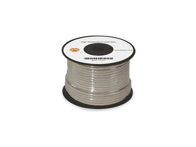
FIG.3 Lead Wire
3) Matters needing attention:
① When the starting and finishing ends are on the same side of the bobbin, a piece of cross tape should be attached before the end of the winding.
② Avoid short circuit when soldering and sleeving.
③ It is the principle that the winding area of the bobbin must be evenly and neatly wound around following the schedule drawing, except for the special regulations and requirements.
④ When there is a Teflon tube and foldback line in the transformer, the Teflon tube added to the entry/exit line must be flush with the groove mouth of the bobbin (or at least 2/3 in height), and it should be routed out of the groove of the bobbin to prevent breaking the wire due to pulling force caused by too long of the tube. However, if the L-shaped pin is wrapped horizontally, the tube should be flush (or at least 2/3 long) with the bobbin edge.
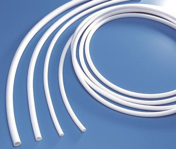
FIG.4 Teflon Tube
⑤ When adding insulating acetate cloth adhesive tape to the transformer, the tape must be close to both sides of the model. In order to avoid the overweight of wrapping wire and high leakage of inductance, it is required that the overlap of acetate cloth tape above 2TS should not exceed 5mm, and that the acetate cloth tape with one layer should be wrapped within 0.9T, leaving a gap to facilitate the penetration of varnishes down to the bottom layer. The choice of the width of the acetate cloth tape is related to the safety regulations of the transformer.
II Wrapping Copper Foils
2.1 Copper Foil Winding Method
1) Types of copper foil and its role in transformers
we have two types of copper foil: bare copper and postage stamp gum. The copper foils covered with a layer of tape is called postage stamp gum, the other one without a layer of tape is called bare copper instead. According to the position in the transformer, it can be divided into inner copper and outer copper. Bare copper is commonly used in outer copper of transformers. The copper foil generally plays a role of shielding in the transformer, mainly to reduce leakage inductance and magnetizing current, and to replace copper wires, acting as conductors when the current passing through the winding is too high.
2) Copper Foil Manufacturing
① General processing method of inner copper foil:
Welding lead wires→The two ends of the copper foil are attached to the center of the acetic acid cloth tape→Folding the tape until it has fully covered the solder joint→Shearing off the tape and the copper foil must remain over 1mm in both sides.
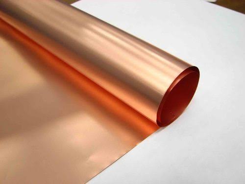
FIG.5 Copper Foil
2.2 Requirements For Using Copper Foil in Transformers
1) Copper foil winding must flatten the edge of the copper foil and avoid doing it at the corner of the bobbin, but must wind the copper foil from the center of the bobbin to prevent the second and first layers from being squeezed, breaking the tape and forming a short circuit.
2) When the inner copper sheet is used as a shield winding between the layers of transformer, its width should cover the winding area of the layer as much as possible. When the thickness of copper foil is less than 0.025mm (1mil), both ends are free from rounding, but when the thickness of it is more than 0.05mm (2mils), both ends must be treated in a round shape.
3) The copper foil must be wrapped flat and not lean to one side or go beyond the bobbin barriers.
4) Outer copper welding.
(3) Considerations
1) Spread the copper foil welding points according to the schedule drawing, and all the copper foils must be wrapped tight and flat, not be biased to one side.
2) Proper amount of tin, smooth welding spot and no prick, what's more, do not solder too long to avoid burning the tape;
3) The thickness of the copper foil for short circuit should be 0.64mm, and the width of it should only be half the width of the copper window winding.
III Pressing Coil
1) Straighten out the copper wires and wrap them around the corresponding pins.
2) Use diagonal pliers to wrap and tighten the copper wire and press it to the bottom of the pin, against the barriers of bobbin.
3) Cut off redundant threads.
4) The number of turns depends on the diameter of coil wire.
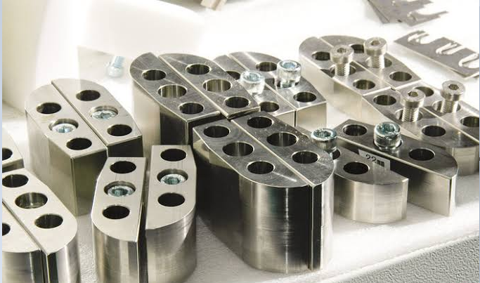
FIG.6 Coils Pressing Machine
Notes: The copper wire shall be closely attached to the base of the pin; it is not allowed to leave wire ends, break the pin, crush the copper wire or damage the model.
In addition, redundant part of copper wire should be cut off.
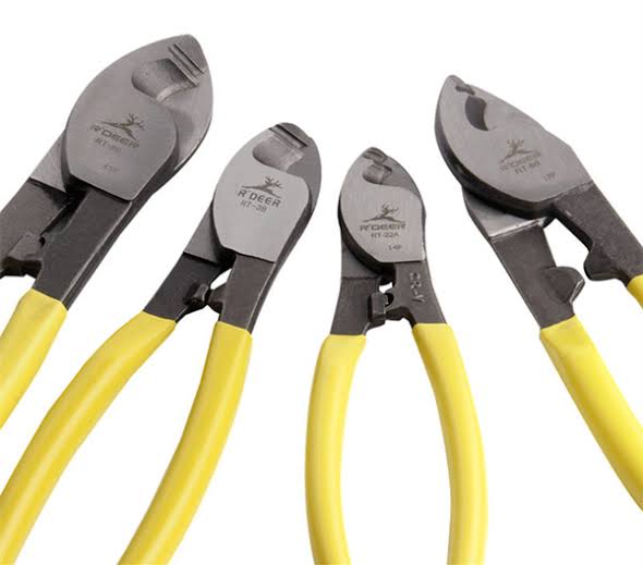
FIG.7 Cut off the Redundant Part of Copper Wire
IV Soldering Tin
4.1 Procedures for Soldering
1) Arrange the products neatly.
2) Pick up a row of products with clamps.
3) Apply soldering flux to the pins.
4) Smooth out tin surface.
5) Soldering tin: about the vertical model, we should insert the pins vertically into solder bath; about the horizontal model, we should insert the pins obliquely into solder bath. The depth of tin plating stays even with the base of the copper pin.
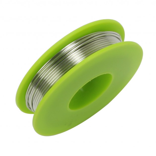
FIG.8 Diagram of Soldering Tin
4.2 Requirements
Tin plating shall be uniform and smooth.
1) It is allowed to tin and leave a soldering iron tip with a length less than 1.5mm when the pin are vertical.
2) When the L-shaped pins are wound in horizontal direction, pin that wound in horizontal direction can not be allowed to tin a tip, but pin that wound in vertical direction can tin a tip with a length less than 1.5mm.
3) The bare part of the PVC wire (multiple strands) can not be marked or broken, or expose the copper wire inside, stained with glue or other impurities after soldering.
4) The soldering flux using must be a neutral solvent.
5) The temperature of tin smelting furnace shall be kept between 450℃ and 500℃, and the soldering time shall vary depending on the diameter of the wire:
AWG Gauge No. large than 30: 1~2s
AWG Gauge No. between 21 to 29: 2~3s
Gauge No. smaller than 20: 3~5s
6) Tin bars in tin smelting furnace have a standard tin-lead ratio of 60/40. New tin needs to be added to the furnace once a month, about a third of the furnace capacity.
7) The tin surface must be scraped and smoothed before a second time soldering.
8) Clean the tin smelting furnace once a week and add the new tin to the furnace until it is full.
4.3 Matters Needing Attention
1) Plastic models are not high-temperature resistant and tend to produce pin shifts;
2) Do not burn out the tape, and the three-layered insulated wire must first be peeled off and then tin-plated;
3) The minimum gap between solder joints must be above 0.5mm.
V Core Assembly
5.1 Processes
1) Core confirmation: unbreakable or deformed;
2) The air gapped core has to be ground and processed first according to the schedule drawing.
3) Assembly: if there is no special provision, the ground core in horizontal model is for the primary end , and that in vertical model is for pin end;
4) The iron core can be fixed by clips, three-layers of tape or epoxy adhesive used at the joints of core drying for half an hour and then bake it in oven at 120℃ for an hour. The color of fixed tapes wrapped around the core should be the same as the color of coils (except for the special requirements). The manufactures should obey the UL Standard.
Notes: Where it begins and where it finishes in the process of core winding; for vertical type, the windings starts and finishes all in the middle; for horizontal type, the windings starts and finishes all at the pin 1; some copper-foil windings starts and finishes at the welding points.
5.2 Matters Needing Attention in Assembling Iron Core
1) when assembling the iron core , the iron cores of different materials cannot be assembled on the same product ;
2) For transformers and inductors with air gap, their gap using shall be in accordance with the air gap method specified in the drawings, and the material placed in the gap shall be capable of withstanding temperature above 130℃. What more, the core shall also be processed and ground;
3) The contact surface between the cores should be kept clean no matter there is a air gap or not, otherwise the inductance will decrease after impregnation.
4) The width of the tapes to wrap a core is specified, with the physical appearance as the priority, the iron core reducing the tape as the second, and the wide gap about 0.3mm~0.7mm as the best.
Checklist for core parameters.pdf
VI Impregnation
6.1 Operating Procedures
1) Place the product neatly on a plate
2) Adjust the concentration of insulating paint (varnishes): 0.915±0.04 .
3) Place the iron plate with products set in the impregnation tank.
4) Start the vacuum impregnation equipment, pump it to 40~50cm/kg, then put in insulating paint, and again pump it to 65~75cm/kg, after 3-5 times continuous pump and vacuum breaking, at last impregnate for 10~15mins, all the procedures will proceed until the product has no bubbles overflow.
5) Deflate and put in insulation paint, then pump to 65~75cm/kg once again; and then deflate, wait until the product is slightly dried, remove and put it for dehydration.
6) The dehydration can be continue over 10mins, until there is no insulation drop from the product.
7) Drying: first, preheat the oven to 80℃ for one hours, and set it to 100 ℃ drying the product for two hours; second, set it to 110℃ drying the product for 4 hours; at the last, unpack the product for confirmation.
8) Remove the product from the oven.
9) Cooling: use a fan to accelerate the cooling.
10) Put it on plates and then send to the production line.
6.2 Matters Needing Attention
1) The proportion of insulating paint and thinner is 2:1
2) When the insulating paint is put in, the height of the insulating paint shall be based on the completely submerged product, but the insulating paint shall not be placed over the copper pins (except for several special types).
VII Labeling (or printing)
1) Label confirmation: Check the contents of the label and make sure there is no missing word on it, the handwriting is clear, and it is not out of date. It is necessary to confirm the correctness of label when words are printing, as shown in figure 9.

FIG.9 What the Tag Contains
2) When labeling, the product should be placed neatly in the same direction. When ejecting ink, the printed surface of the product should be directed toward the nozzle and placed on the conveyor belt. The product must be placed right.
3) Item and hazard labels shall be placed, stamped or pasted as required on the drawings. The label "DANGER","HIGH VOLTAGE"or the lightning symbol shall be attached to the upper center of the transformer. The arrow direction of the "DANGER" label is towards the primary winding of the transformer, as shown in figure 10.

FIG.10 Diagram of Labels
4) Notes: The label must be flat and pressed by hand to make full contact with the product. The label should not be error-affixed or missed.
VIII Exterior
The exterior check includes the following aspects:
(1) Verify that the product is complete
1) Whether there are cracks or disconnections in the model;
2) Whether the core is broken;
3) Whether the tape is punctured;
4) Whether the tube is damaged or too short;
5) Whether or not cut the wrong foot.
(2) Remove dirt
1) After the impregnation, no glue (insulation paint solids) shall be left around the core of the transformer so that the transformer can be flatly attached to the PCB (Printed Circuit Board), or the adhesive label can be smoothly affixed to;
2) Remove copper and tin residues.
(3) Horizontal core can not be inclined after impregnation of insulating paint (wire-wrapping is not allowed to beyond the bobbin).
(4) For a transformer(STAND-OFF) marked three spots, which must be affixed flat on PCB when inserted into it.
(5) The iron core should never be loosened.
(6) Pins should be vertical and smooth, no loose or break or any marks.
(7) Pins can not be bent, and its inner copper can not be exposed to air result in oxidation; the intervals (PITCH) and the pin length of bobbins shall be based on the drawings.
(8) Check that the tin soldering is all completed.
(9) Check that the labels are all affixed correct.
(10) Check that all spots are made clear and are on the right positions.
(11) Defective product must be repaired or scrapped if it cannot be repaired.
(12) Tapes repair: If the outermost layer of tape is damaged and the coil is exposed, it must use the adhesive tape again to completely cover the exposed area. The number of layers of adhesive tape must be the same as that of the original outermost layer of adhesive tape, and must be dried after applying insulating paint. Both ends of the attached adhesive tape shall extend into both sides of the iron core, and the length of the tape shall not exceed the thickness of the iron core (at least 2/3 of iron core thickness).
IX Electrical Test
Electrical testing mainly includes the following three aspects:
(1) Measuring the inductance of the main coil; during semi-finished product testing, the range of inductance should be reduced appropriately.
(2) Measuring the number of turns and the phase.
X Book Suggestions
1. Handbook of Coil Winding: Technologies for efficient electrical wound products and their automated production 1st ed. 2018 Edition
This book presents the current coil winding methods, their associated technologies and the associated automation techniques. From the introduction as a forming joining process, over the physical properties of coils, the semifinished products (wire, coil body, insulation) are introduced. In the process chain, different winding methods are used for magnet wire winding. Finally, the automation of these processes is described.
by Jürgen Hagedorn and Florian Sell-Le Blanc
2. Detection of Interdisc Faults in the Windings of Power TransformerFeb 27, 2018
In extra high voltage power transmission, power transformer is the most important component. Insulation failure within transformer is considered to be one of the most important causes of failure of power transformer. Comparison of neutral currents at reduced and full voltages was carried out for detection of fault in a power transformer winding during impulse test. In order to assess the integrity of the winding, high voltage power transformers were subjected to full and chopped impulse voltages of specified values in accordance with the standard requirement. One of the tests carried out was the comparison of applied voltage and a resultant neutral current signal at reduced and full voltage levels. The difference in wave shape of the recorded current and voltage signal confirmed the existence of fault in the transformer winding.
by Sridhar Patthi and B. P. Singh
3. Novel high frequency model of transformers of electronic devices: Development of a novel regular, high frequency modell for small size transformersDec 24, 2012
A high frequency model of transformer shielding is proposed for the use with circuit simulator software modelling the high frequency behaviour of the shielding. A comprehensive model containing the proposed elements can help in evaluating electromagnetic compatibility (EMC) of a future transformer during its design period.
by György Elmer
You May Also Like:
Switched Mode Power Supply Design: SMPS Power Loss & Efficiency
What is Pulse Width Modulation(PWM)
PCB Layout Tips and Tricks: The Components and Wires
MOSFET Basics, Working Principle and Applications & Advantages
Ordering & Quality
| Photo | Mfr. Part # | Company | Description | Package | Qty |
|
MBRS130LT3G | Company:ON Semiconductor | Remark:DIODE SCHOTTKY 30V 2A SMB | Package:SMB |
MBRS130LT3G Datasheet |
In Stock:516247 Inquiry |
Inquiry |
|
MR82C54 | Company:NTERSIL | Remark: | Package:CLCC |
MR82C54 Datasheet |
In Stock:455 Inquiry |
Inquiry |
|
FAN7071 | Company:FAIRCHILD | Remark:IC LANDING CORRECTION 10SIPH | Package:10-SIP, 10-SIPH |
FAN7071 Datasheet |
In Stock:5920 Inquiry |
Inquiry |

|
MC908QB4CDWE | Company:NXP | Remark:IC MCU 8BIT 4KB FLASH 16SOIC | Package:16-SOIC (0.295", 7.50mm Width) |
MC908QB4CDWE Datasheet |
In Stock:3816 Inquiry |
Inquiry |
|
MC9S08QA2CFQE | Company:NXP | Remark:IC MCU 8BIT 2KB FLASH 8QFN | Package:8-VDFN Exposed Pad |
MC9S08QA2CFQE Datasheet |
In Stock:25275 Inquiry |
Inquiry |

|
MRF6S9130HR5 | Company:FREESCALE | Remark:NA | Package: |
MRF6S9130HR5 Datasheet |
In Stock:440 Inquiry |
Inquiry |
|
MRF373ALR1 | Company:FREESCALE | Remark:RF Mosfet LDMOS 32V 200mA 860MHz 18.2dB 75W NI-360 | Package:TO-63 |
MRF373ALR1 Datasheet |
In Stock:85 Inquiry |
Inquiry |
|
MC145484DW | Company:NXP / Freescale | Remark:IC 5V PCM CODEC-FILTER 20-SOIC W | Package:20-SOIC (0.295", 7.50mm Width) |
MC145484DW Datasheet |
In Stock:38288 Inquiry |
Inquiry |

|
HCS200-I/SN | Company:Microchip Technology | Remark:IC CODE HOPP ENCODER 7FUNC 8SOIC | Package:8-SOIC (0.154", 3.90mm Width) |
HCS200-I/SN Datasheet |
In Stock:506 Inquiry |
Inquiry |
|
TMMBAT46FILM | Company:STMicroelectronics | Remark:DIODE SCHOTTKY 100V 150MA MINMLF | Package:DO-213AA (Glass) |
TMMBAT46FILM Datasheet |
In Stock:48488 Inquiry |
Inquiry |